Fully-automatic back-flushing type self-cleaning filter

A self-cleaning filter and backwashing technology, applied in the field of water treatment, can solve the problems of inability to clean on-line, low degree of automation, huge system system, etc., and achieve the effects of overload protection, high degree of automation and large filtering area.

Inactive Publication Date: 2013-02-13
JIANGSU UNIV OF SCI & TECH
View PDF4 Cites 12 Cited by
  • Summary
  • Abstract
  • Description
  • Claims
  • Application Information

AI Technical Summary

Problems solved by technology

Commonly used backwashing self-cleaning filter structures are: one is to use multiple filters in parallel and use them separately. When the filter in working condition needs to be cleaned, stop the work of the filter and start another filter at the same time. The disadvantage is that it increases the cost of the system. Cost, huge system, low degree of automation, need for manual cleaning, consume a lot of manpower and material resources
The second is to open the bypass inlet to change the direction of the imported water passing through the filter, that is, to use unfiltered water to reverse the filter. The disadvantage is that the cleaning is not thorough, the water consumption is large, and it cannot be cleaned online.
The third is that multiple filter units are installed in the filter cylinder to clean one by one. The disadvantage is that when a filter unit has not been thoroughly cleaned, the continuously rotating motor will drive the cleaning arm to turn away, resulting in incomplete cleaning and consumption. large amount of water

Method used


Image

  • Fully-automatic back-flushing type self-cleaning filter
  • Fully-automatic back-flushing type self-cleaning filter
  • Fully-automatic back-flushing type self-cleaning filter

Examples


Embodiment Construction

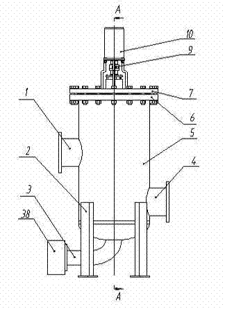
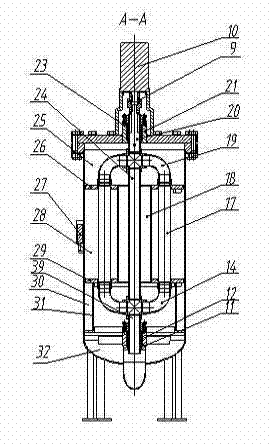
[0019] Such as figure 1 and figure 2 As shown, the fully automatic backwashing self-cleaning filter of the present invention includes a cylindrical cylinder body 5, the bottom of the cylinder body 5 is fixedly supported on the support 2, and the side wall of the cylinder body 5 is provided with a water inlet 4 With the water outlet 1, the water inlet 4 and the water outlet 1 are distributed on both sides of the axis of the cylinder 5, and the water inlet 4 is below the water outlet 1. A differential pressure sensor 27 is installed near the water inlet 4 and the water outlet 1, the differential pressure sensor 27 is connected to the controller, and the differential pressure sensor 27 can be contained in a box welded with the outer wall of the cylindrical shell 5. The bottom port of the cylinder body 5 is sealed and connected with the elliptical head 32, and is sealed with the elliptical head 32. The sewage pipe 3 stretches out from the lower end of the oval head 32 . The to...


PUM


Abstract

The invention discloses a fully-automatic back-flushing type self-cleaning filter. An inner cavity of a barrel body is divided into an upper cavity, a middle cavity and a lower cavity by an upper separating plate and a lower separating plate. In the middle cavity, two ends of a middle diversion pipe are respectively connected with big ladder center holes in the upper separating plate and the lower separating plate in sealed mode, and two ends of each of eight thin cylinder filter screens are respectively connected with eight small ladder holes in the upper separating plate and the lower separating plate in sealed mode. A middle blow-off pipe is sleeved in the middle diversion pipe in non-contact mode. An upper rotary arm is arranged in the upper cavity, and a lower rotary arm is arranged in the lower cavity. The upper rotary arm and the lower rotary arm are respectively composed of a four-way connector, two elbow pipes which are symmetrically connected with the left end and the right end of the four-way connector, and sealing covers connected with lower end faces of the elbow pipes. The upper end of the middle blow-off pipe is connected with the lower end of the four-way connector of the upper rotary arm, and the lower end of the middle blow-off pipe is connected with the upper end of the four-way connector of the lower rotary arm. The spacing between the two sealing covers on the same rotary arm is equal to the diameter of a circumference where the eight small ladder holes are located. The upper end of the four-way connector of the upper rotary arm is fixedly connected with a rotary arm drive shaft driven by a stepping motor. The thin cylinder filter screens are back-flushed automatically so that the back-flushing effect is good.

Description

technical field [0001] The invention relates to a filter in the field of water treatment, in particular to a fully automatic backwashing self-cleaning filter. Background technique [0002] The self-cleaning process of the backwash self-cleaning filter is to reverse the flow of the fluid in the system, wash and strip the filter residue from the surface of the filter screen, and then discharge it. There is usually no other device in the filter screen. Commonly used backwashing self-cleaning filter structures are: one is to use multiple filters in parallel and use them separately. When the filter in working condition needs to be cleaned, stop the work of the filter and start another filter at the same time. The disadvantage is that it increases the cost of the system. Cost, huge system, low degree of automation, need for manual cleaning, consume a lot of manpower and material resources. The second is to adopt a bypass inlet to change the direction of the imported water passing...

Claims


Application Information

Patent Timeline
Patent Type & Authority Applications(China)
IPC IPC(8): B01D36/00B01D29/52B01D29/66B01D29/33
Inventor 陈宁佘建国孟宪振孙玉可焦晨
Owner JIANGSU UNIV OF SCI & TECH
Why Eureka
Try Eureka