Valve steel plate element straightener

A technology of element straightening machine and straightening mechanism, which is applied in the field of metal wire processing equipment, can solve the problems of low yield, low work efficiency, easy to scratch, etc., and achieve high sizing accuracy, low labor intensity, and straightening accuracy high effect

Active Publication Date: 2013-02-13
JIANGSU SHENYUAN SPECIAL STEEL
View PDF4 Cites 7 Cited by
  • Summary
  • Abstract
  • Description
  • Claims
  • Application Information

AI Technical Summary

Problems solved by technology

However, when the existing straightening machine straightens the valve steel disc element, either the surface of the valve steel wire rod is easy to scratch, or the straightness of the valve steel wire rod is not straight. The reason is that the counter rolls of the straightening machine are nodular The hardness of cast iron is HRC≤20, while the hardness of valve steel is about 40. When straightening, nodular cast iron has a poor straightening effect on valve steel wire. If the material of the counter roller is changed to a material with a hardness of HRC of 40, The scratches on the surface of the valve steel wire will be more serious
At the same time, valve steel is an important material used in the automotive field, and the quality requirements for valve steel are constantly improving. Not only is the surface of valve steel required to be free of scratches, but also the straightening accuracy is required to be below 0.5 mm / m. The machine cannot meet the requirements
At the same time, the existing gas valve steel disc element straightening machine cannot be fixed to length, the labor intensity of the workers is high, and the work efficiency is low. Now, due to the improvement of the utilization rate of the gas valve steel wire rod by users, there is a fixed length for the gas valve steel wire rod. Requirements, and the existing air valve steel disc element straightening machine cannot straighten the remaining steel wire, resulting in waste and low yield

Method used


Image

  • Valve steel plate element straightener
  • Valve steel plate element straightener
  • Valve steel plate element straightener

Examples


Embodiment Construction

[0016] The present invention will be further described below in conjunction with the accompanying drawings and specific embodiments.

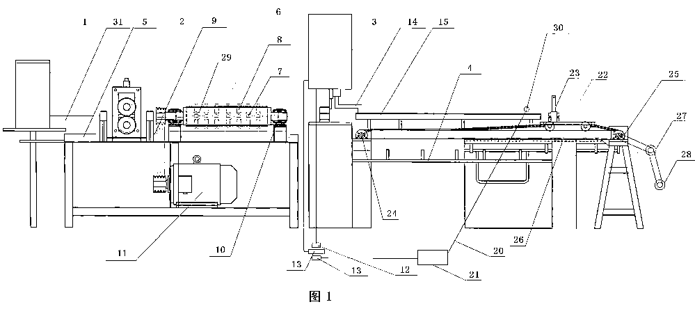
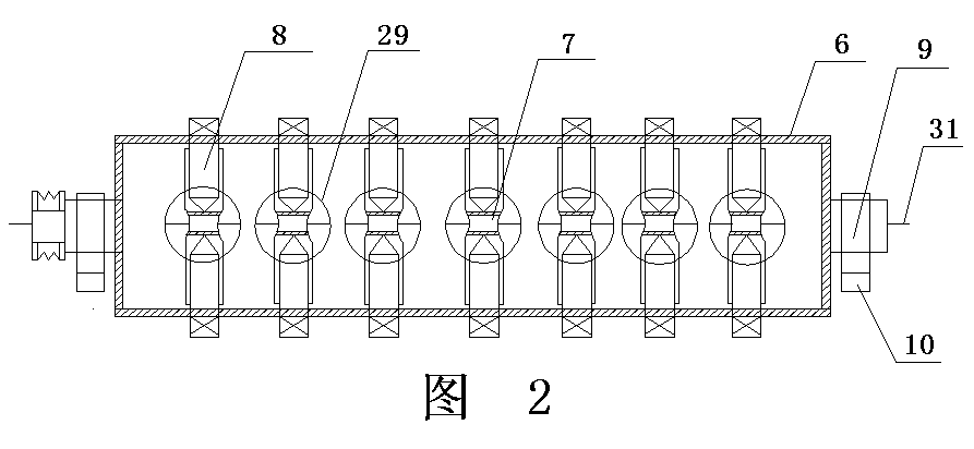
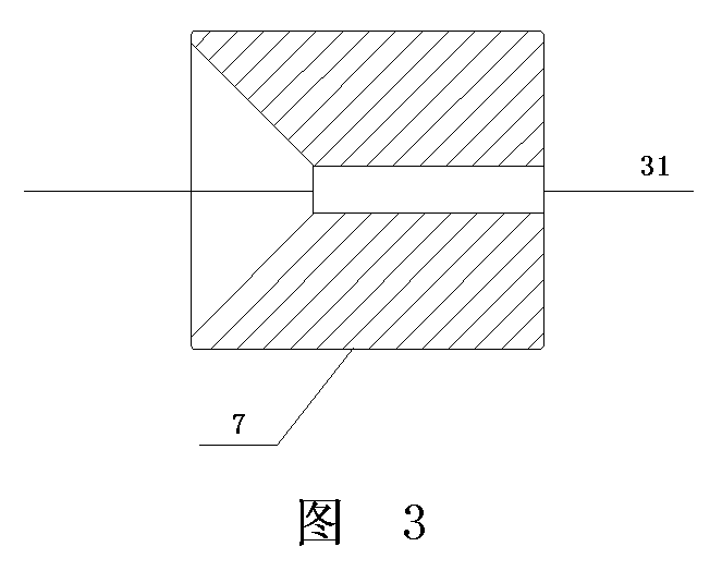
[0017] Such as figure 1 , figure 2 , image 3 , Figure 4 Shown, a kind of air valve steel disc element straightening machine comprises pay-off reel 1, pinch roller 1, straightening mechanism and cut-off mechanism, described pay-off reel 1, pinch roller 2, straightening mechanism, cut-off mechanism Mechanisms are arranged on the main frame platform 5 in turn, and the straightening mechanism includes a straightening cylinder 6 arranged horizontally, and seven straightening molds 7 are arranged in the straightening cylinder 6, and each straightening mold 7 passes through the upper and lower Two symmetrical adjustable top bolts 8 are horizontally fixed in the straightening cylinder 6. The straightening mold 7 is a cylindrical structure, and the two ends of the straightening cylinder 6 are provided with a rotating shaft with a through hole in t...


PUM


Abstract

The invention discloses a valve steel plate element straightener which comprises a pay-off reel, a pinch roll, a straightening mechanism and a cut-off mechanism, wherein the straightening mechanism comprises a straightening barrel which is horizontally arranged, at least one straightening model is arranged in the straightening barrel, the straightening model is horizontally fixed in the straightening barrel by two adjustable jacking bolts symmetrical to each other vertically and has a cylinder structure, the outer sides of two ends of the straightening barrel are provided with rotating shafts with through holes at the center, the rotating shafts are arranged on a support frame, the support frame is fixed on a main frame table, and any of the rotating shafts is connected with the shaft of the motor by a transmission mechanism. The valve steel plate element straightener has the advantages of simple structure, low cost, easy operation, convenient overhauling, no scratch on the surface of wire, high straightening precision, automatic sizing, cutting-off and blanking, high sizing precision, low labor intensity, high efficiency, no balance of straightening steel wires, and high yield.

Description

technical field [0001] The invention relates to the field of metal wire processing equipment, in particular to a gas valve steel disc element straightening machine. Background technique [0002] In the field of metal wire straightening, with the rapid development of industrial technology, all walks of life have higher and higher quality requirements for the basic raw material - metal wire, especially for the straightness of bars, wires, and pipes. requirements, while the straightening accuracy of the current straightening machine in my country mostly stays above 1mm / m. Existing straightening machines such as hyperbolic roller straightening machines utilize upper and lower pairs of rollers to straighten general metal wires, and can achieve better results. However, when the existing straightening machine straightens the valve steel disc element, either the surface of the valve steel wire rod is easy to scratch, or the straightness of the valve steel wire rod is not straight. T...

Claims


Application Information

Patent Timeline
Patent Type & Authority Applications(China)
IPC IPC(8): B21F1/02B21F11/00
Inventor 赵京甸刘卫东戴金根叶刚成义军汪维国练明生夏友春
Owner JIANGSU SHENYUAN SPECIAL STEEL
Why Eureka
Try Eureka