Method for operating a laser scanner and processing system with laser scanner

A technology of laser scanners and processing systems, applied in laser welding equipment, metal processing equipment, manufacturing tools, etc., can solve problems such as prolonging processing time

Active Publication Date: 2013-02-13
CARL ZEISS MICROSCOPY GMBH
View PDF7 Cites 5 Cited by
  • Summary
  • Abstract
  • Description
  • Claims
  • Application Information

AI Technical Summary

Problems solved by technology

[0006] Determining the position of the aperture relative to the laser scanner based on the signal detected by the detector...

Method used


Image

  • Method for operating a laser scanner and processing system with laser scanner
  • Method for operating a laser scanner and processing system with laser scanner
  • Method for operating a laser scanner and processing system with laser scanner

Examples


Embodiment Construction

[0028] In the example embodiments described below, components with the same function and structure are marked with the same reference numerals as much as possible. Therefore, in order to understand the characteristics of individual components of a particular embodiment, reference should be made to the description of other embodiments of the invention and the summary.

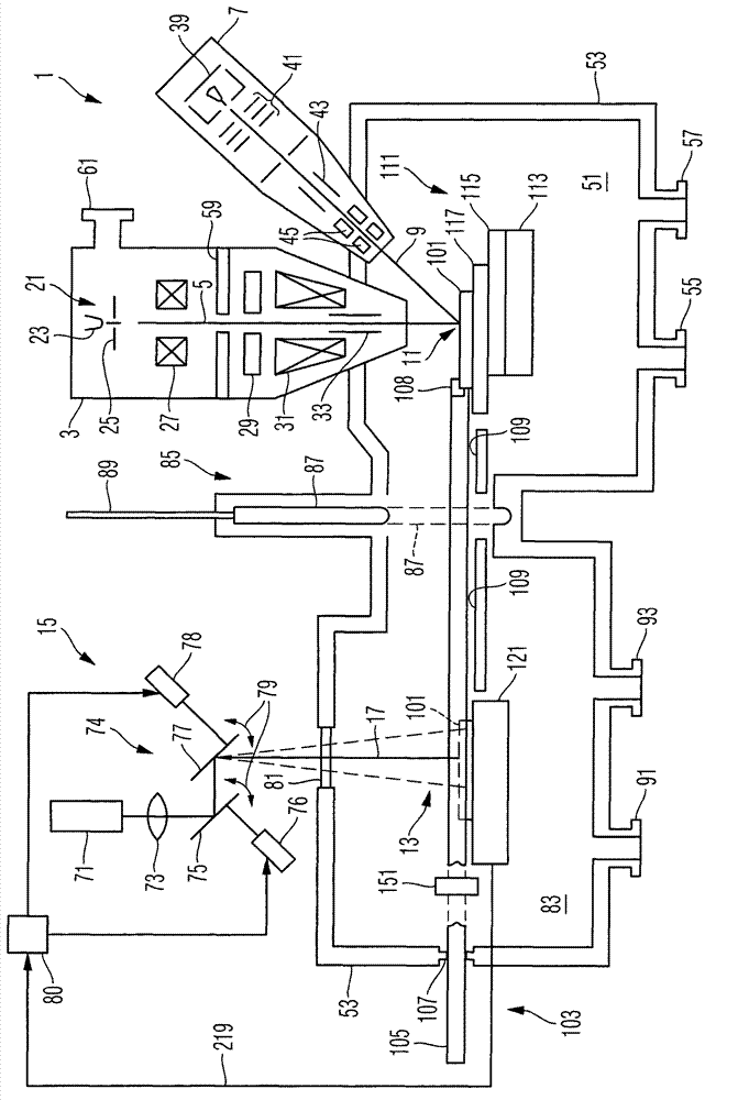
[0029] figure 1 is a schematic diagram of the processing system 1 . The machining system is configured to perform machining of an object using a laser beam and using a multi-particle beam. Background information on such a system can be found, for example, in US2011 / 0198326A1, the entire disclosure of which is incorporated in this patent application by reference.

[0030] The processing system 1 includes two particle beam columns, that is, an electron beam column 3 that generates an electron beam 5 , and an ion beam column 7 that generates an ion beam 9 . The ion beam 9 is directed to a processing area 11 like ...


PUM


Abstract

A method includes using a scanner to scan a laser beam along a scan path, and detecting light intensities caused by laser light of the laser beam incident on a detection cross-section. The method also includes determining a position of the detection cross-section relative to the laser scanner based on the detected light intensities. The scan path includes, in a plane which includes the detection cross-section, a first partial path and a second partial path which extend adjacent to each other and at a distance from each other which is: a) smaller than a diameter of the detection cross-section plus a diameter of the laser beam in the plane which includes the detection cross-section; and b) greater than 0.3 times the diameter of the laser beam in the plane which includes the detection cross-section or greater than 0.3 times the diameter of the detection cross-section.

Description

[0001] Cross References to Related Applications [0002] This application claims priority to patent application No. 102011109449.4, filed in Germany on August 4, 2011, entitled "Method for calibrating a laser scanner and processing system with a laser scanner", the contents of which are hereby incorporated by reference in their entirety . technical field [0003] The invention relates to a method of operating a laser scanner and a machining system having a laser scanner. In particular, the invention relates to methods of calibrating laser scanners. Background technique [0004] It is known to use laser beams to process objects, for example to change the material properties of an object, or to remove material from an object. For this purpose, a laser beam with sufficiently high beam energy and sufficient photon energy is guided by a laser scanner onto the previously determined processing position of the object. This is achieved by setting the scan deflection of the laser s...

Claims


Application Information

Patent Timeline
IPC IPC(8): B23K26/00B23K26/02
CPCB23K26/0807B23K26/041B23K26/426B23K26/122B23K26/032H01J2237/30433B23K26/1224B23K26/082B23K26/042B23K26/705
Inventor H·多默R·罗森克兰兹
Owner CARL ZEISS MICROSCOPY GMBH
Why Eureka
Try Eureka