Oil level monitoring system for an internal combustion engine

一种内燃机、起动内燃机的技术,应用在机械设备、发动机控制、燃料喷射控制等方向,能够解决很难确定等问题

Inactive Publication Date: 2009-09-09
WACKER NEUSON SE
View PDF4 Cites 8 Cited by
  • Summary
  • Abstract
  • Description
  • Claims
  • Application Information

AI Technical Summary

Problems solved by technology

Correspondingly, it is difficult to determine whether there is enough oil for lubricating the internal combustion engine with known monitoring systems

Method used


Image

  • Oil level monitoring system for an internal combustion engine
  • Oil level monitoring system for an internal combustion engine
  • Oil level monitoring system for an internal combustion engine

Examples


Embodiment Construction

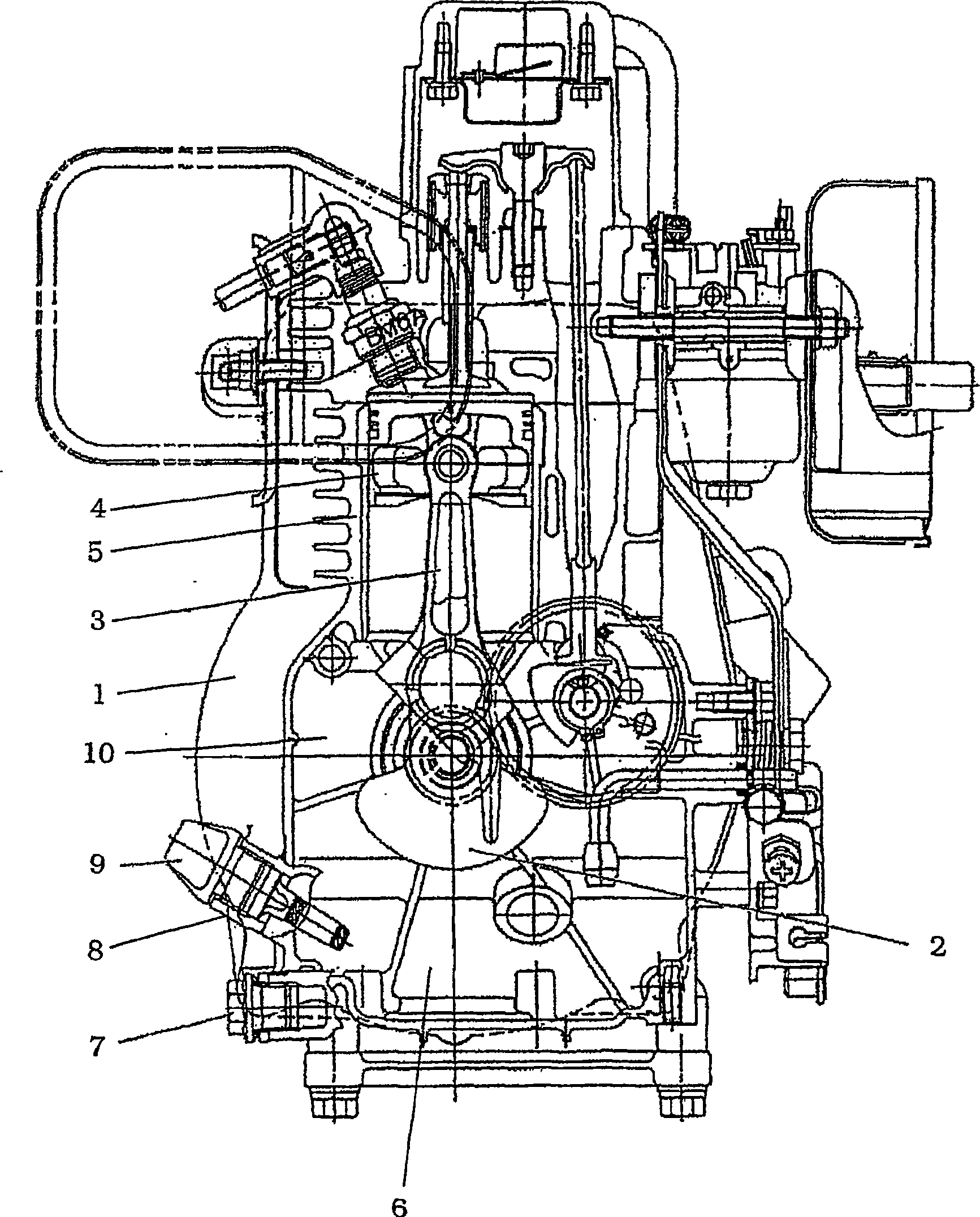
[0044] Attached figure 1 A well-known internal combustion engine is shown in, so only a brief description will be given below. The internal combustion engine is basically suitable for dispersing lubricated engines, that is to say, for example, a four-stroke gasoline engine or a diesel engine.

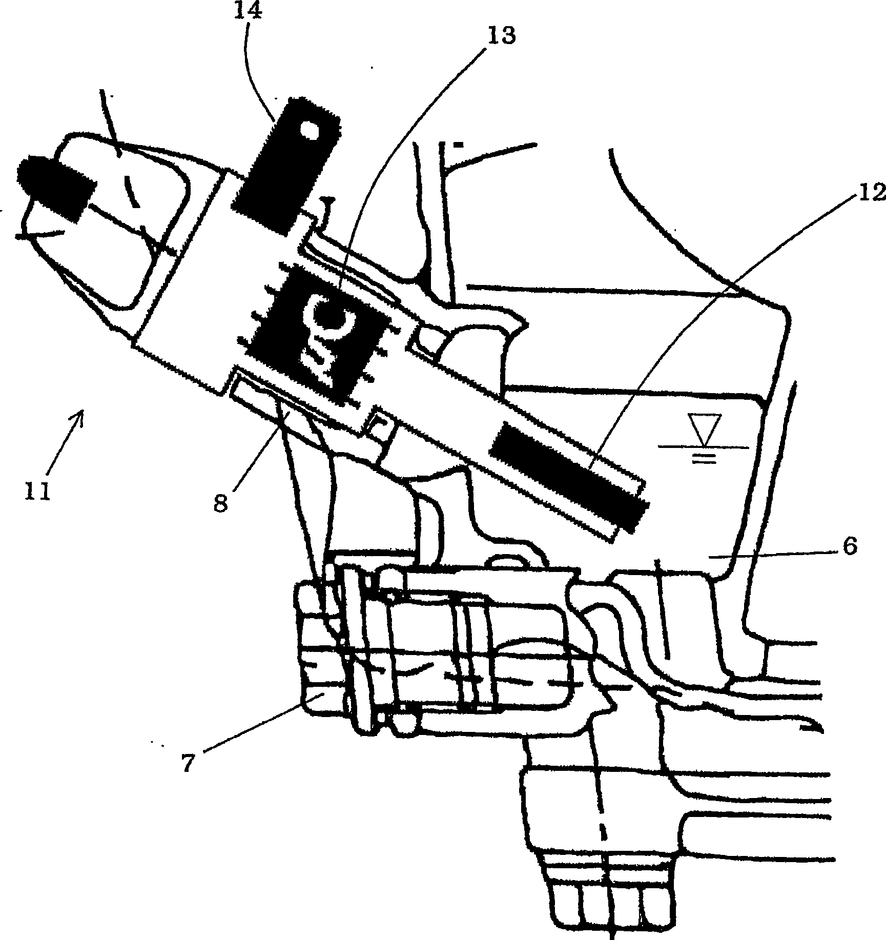
[0045] A crankshaft 2 is rotatably supported in the engine case 1, and at least one connecting rod 3 is rotatably supported on it. The other end of the connecting rod 3 is connected with a piston 4 which can reciprocate axially in the cylinder 5. There is an oil storage tank 6 (oil basin, oil tank) under the crankshaft, which collects lubricating oil. When the oil is dirty or exhausted, the oil can flow out of the oil drain hole 7.

[0046] Attached figure 1 In the illustrated internal combustion engine, a static oil pressure switch 9 is installed in a threaded hole 8 preset in the engine housing 1. One disadvantage of the static oil pressure switch 9 is that it works like a float in prin...


PUM


Abstract

The internal combustion engine in a device has an oil reservoir (6) in the region of the crankcase (10) for containing oil. An oil detection device (12) is used to detect the oil present in the oil tank (6) and to generate a corresponding signal, which is evaluated by an evaluation device (13). Preferably, the oil level information is only generated when the internal combustion engine is started or within a certain period of time after starting the internal combustion engine. If the internal combustion engine has reached its operating speed, no further oil level monitoring takes place.

Description

Technical field [0001] The invention relates to a device with an internal combustion engine and a method for monitoring the oil level in the internal combustion engine. Background technique [0002] Internal combustion engines, especially four-stroke gasoline engines or diesel engines, require sufficient oil storage to achieve the correct lubrication function. The storage of oil is composed of the oil in the oil storage tank. This oil storage tank is mostly located near the crankcase, so that it is lubricated by centrifugal type, but it also distributes oil for lubricating cylinders, pistons, bearings and other locations through an additional oil pump. [0003] Here, the presence or absence of lubricating oil necessary for engine lubrication is checked, for example, by an oil dipstick or by different sensors (for example, an oil pressure switch in the case of oil pump lubrication). Sensors can be used in the monitoring circuit in this way: they turn off the engine when it is dete...

Claims


Application Information

Patent Timeline
Patent Type & Authority Patents(China)
IPC IPC(8): F01M11/12F01M1/18F01MF02D41/06
CPCF01M11/12F01M1/18
Inventor M·斯太芬
Owner WACKER NEUSON SE
Why Eureka
Try Eureka