
Adjustable rotation polishing machine

A polishing machine and adjustable technology, applied in the field of machine tools, can solve the problems of increased labor intensity, high processing cost, lack of positioning devices, etc., and achieve the effects of reducing labor intensity, good locking function, and expanding the scope of application

Inactive Publication Date: 2013-02-13
天津市诺恩电器设备制造有限公司
View PDF6 Cites 16 Cited by
  • Summary
  • Abstract
  • Description
  • Claims
  • Application Information

AI Technical Summary

Problems solved by technology

[0003] Since the metal container is usually a complete set of equipment, it is polished by a combination of mechanical polishing and manual polishing, which not only causes a large difference in the appearance quality of the workpiece, but also affects the overall processing quality of the entire equipment, and the processing range of polishing is limited. ; And the polishing production efficiency is low; the labor intensity of the workers is high, and the processing cost is high
[0004] In addition, due to the lack of positioning devices on the rotary table of the polishing machine, it is very easy to deviate when polishing the inner surface of the curved metal container head, and often requires manual auxiliary positioning, which not only increases labor intensity, There are also certain security risks

Method used


Image

  • Adjustable rotation polishing machine
  • Adjustable rotation polishing machine
  • Adjustable rotation polishing machine

Examples


Embodiment Construction

[0021] The present invention will be further described in detail below in conjunction with the accompanying drawings. The following embodiments are only descriptive, not restrictive, and cannot limit the protection scope of the present invention.

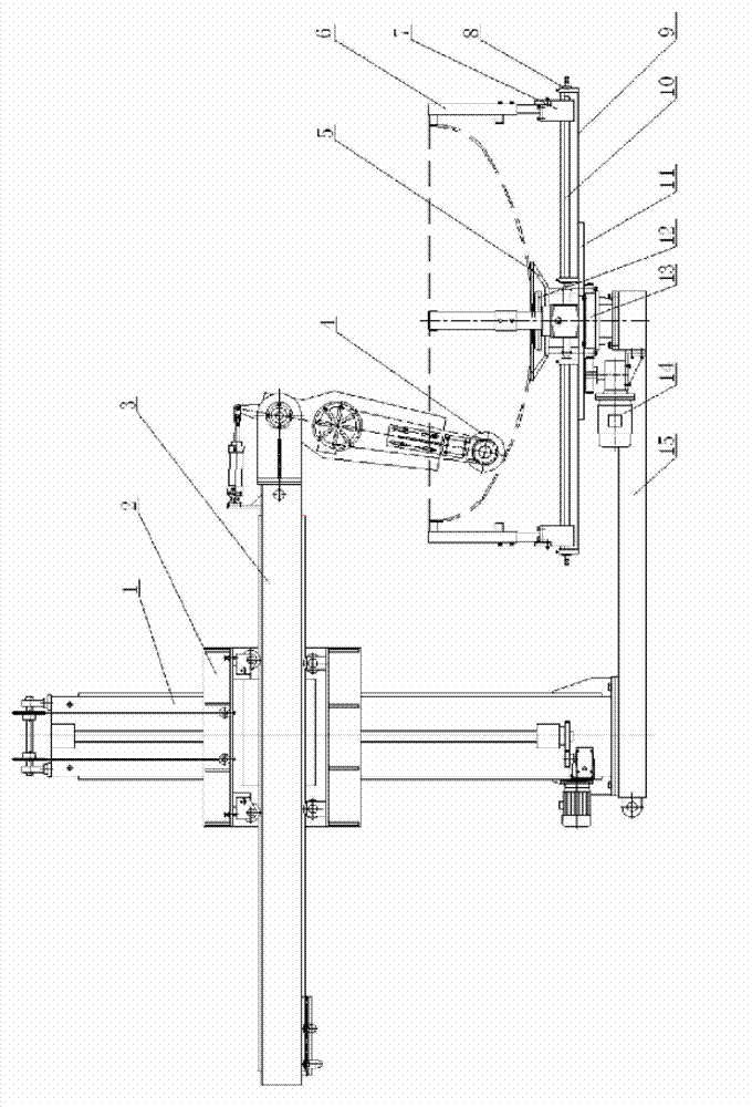
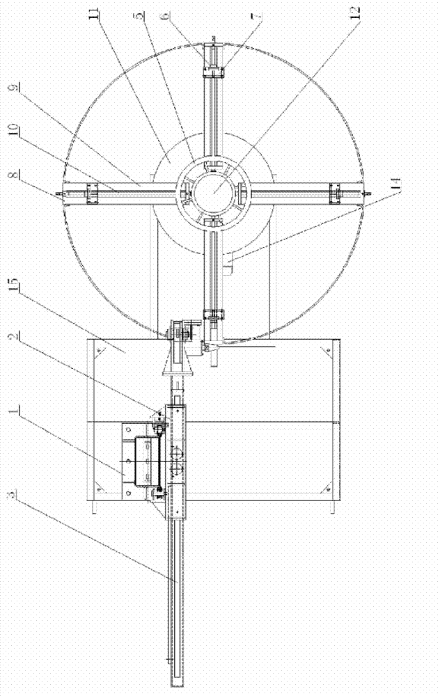
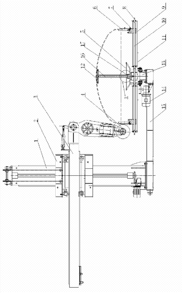
[0022] An adjustable rotary polishing machine, comprising a base 15, a lifting column 1, a horizontal guide rail 3, a polishing head 4 and a rotary worktable, a vertically fixed lifting column is mounted on the base, and a slider 2 runs vertically on the lifting column. A horizontal guide rail is horizontally slid on the slider, and the polishing head is hinged at the end of the guide rail. A rotary table is installed on the base corresponding to the bottom of the polishing head. The rotary table includes a rotary support seat 13 and a rotating disk 11. The seat is installed on the base, and the horizontal coaxial rotating disk is installed on the rotating support base. A motor 14 is installed on the base, and the motor drives the ro...


PUM


Abstract

The invention relates to an adjustable rotation polishing machine, which comprises a base, a lift column, a horizontal guide rail, a polishing head and a rotation workbench, wherein the lift column is vertically and fixedly arranged on the base, a sliding block is vertically guided to run on the lift column, the horizontal guide rail is arranged on the sliding block in a horizontal sliding way, the end part of the guide rail is hinged with the polishing head, the rotation workbench is arranged on the base corresponding to a place below the polishing head, a plurality of screw rod frames are radially, uniformly and centripetally distributed on the surface of the rotation workbench, the front end and the rear end of each screw rod frame are fixedly provided with a bearing seat respectively, a screw rod is coaxially arranged between two corresponding bearing seats, a sliding block runs on each screw rod in an engagement manner, and a limitation plate is vertically and upwards arranged on each sliding block. In the polishing machine, a clamping device is additionally arranged on the rotation workbench, and by synergistic coordination between the displacement of each sliding block and the self-locking function of each screw rod, the clamping device not only can be adjusted in clamping size size but also has a good locking function.

Description

technical field [0001] The invention belongs to the field of machine tools, and relates to a polishing machine, in particular to an adjustable rotary polishing machine. Background technique [0002] The polishing machine is widely used in the processing of metal workpieces, especially the polishing of the head of the metal container. The polishing machine is usually composed of an electrical control part and a host part. The host part consists of a base, a lifting mechanism, a horizontal mechanism, a polishing head, a rotating working Taiwan composition. The polishing machine mentioned above is mainly aimed at polishing the inner and outer surfaces of metal container heads, especially the inner and outer surfaces of curved metal container heads. All polishing methods are manually polished. [0003] Since the metal container is usually a complete set of equipment, it is polished by a combination of mechanical polishing and manual polishing, which not only causes a large dif...

Claims


Application Information

Patent Timeline
IPC IPC(8): B24B29/02B24B41/06B24B41/00
Inventor 郭益年李恩勇
Owner 天津市诺恩电器设备制造有限公司
Learn More