
Manufacturing method of composite hose

A manufacturing method and technology for composite hoses, applied in the field of hoses, can solve problems such as affecting bonding strength, difficult to manufacture, and easily damaged outer pipes, and achieve the effects of avoiding compression deformation and reliable bonding

Active Publication Date: 2013-02-13
JINHUA CHUNGUANG RUBBER & PLASTIC HOSE
View PDF6 Cites 2 Cited by
  • Summary
  • Abstract
  • Description
  • Claims
  • Application Information

AI Technical Summary

Problems solved by technology

The disadvantages of this technical solution are: 1) it is necessary to compress the large-diameter pipe to make it contact with the small-diameter pipe after deformation, so the outer pipe is easily damaged, especially when the diameter difference between the inner and outer pipes is large; 2) The inner and outer pipes are bonded when the large-diameter pipe is under pressure and deformation. When the external pressure is released, there will be internal stress at the bonding place, which will affect the bonding strength.
Although this technical solution can avoid the deformation and damage of the hose, and there is basically no deformation stress at the bonding point, the above technical solution is difficult to manufacture due to process limitations when the inner diameter of the large-diameter tube is close to the outer diameter of the small-diameter tube.

Method used


Image

  • Manufacturing method of composite hose
  • Manufacturing method of composite hose

Examples


Embodiment 1

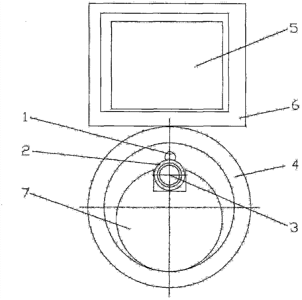
[0017] The composite hose manufacturing method of the present embodiment can be found in figure 1 ,Proceed as follows:

[0018] The first step is to use extrusion and injection molding machines to apply viscose 1 along the length direction on the outer surface of the small-diameter tube 2 to form a line, and insert it together with the iron rod 3 inserted in the small-diameter tube and the support rod 7 for placing the small-diameter tube in the gap Inside the large diameter tube.

[0019] In the second step, the electromagnetic frame 6 equipped with the electromagnet 5 is approached to the large-diameter tube 4 toward the side of the small-diameter tube 2 coated with the glue 1, and is attracted to each other with the iron rod 3, so that the small-diameter tube 2 is coated with the outer surface of the viscose 1 It is in close contact with the inner surface of the large-diameter pipe 4 .

[0020] In the third step, after the inner surface of the small-diameter tube 2 and th...

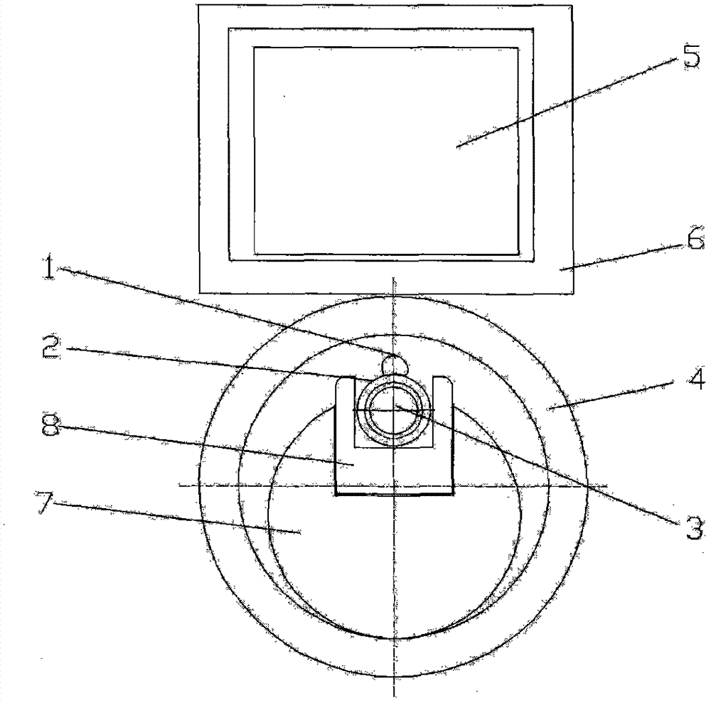
Embodiment 2

[0023] The composite hose manufacturing method of the present embodiment can be found in figure 2 , the basic steps are the same as in Embodiment 1, the glue is hot melt glue, the main difference is that the small-diameter tube 2 inserted with the iron rod 3 is embedded in the groove of the magnetic groove 8 and is located in the gap of the support rod 7, and the small-diameter tube The diameter of 2 matches the width and depth of the groove. When the external electromagnetic frame approaches the large-diameter tube 4 toward the hot-melt adhesive on the small-diameter tube 2, it will attract each other with the iron rod 3 and the magnetic groove 8, so that the outer surface of the small-diameter tube 2 coated with the hot-melt adhesive 1 and the large-diameter tube The inner surfaces of 4 are in close contact. After the hot melt adhesive makes the small-diameter tube 2 adhere to the inner surface of the large-diameter tube 4, remove the electromagnetic frame, and pull out th...


PUM


Abstract

The invention relates to a manufacturing method of a composite hose, and belongs to the technical field of hoses. The method comprises the steps of: 1, coating mucilage glue on a small-diameter pipe along the length direction of the outer surface to form a line, and inserting the small-diameter pipe into a large-diameter pipe together with a magnetic metal rod inserted into the small-diameter pipe; 2, enabling an electromagnetic rack provided with an electromagnet to approach the large-diameter pipe towards one side of the small-diameter pipe coated with the mucilage glue, so as to attract one another together with the magnetic metal rod, so that the outer surface of the small-diameter pipe coated with the mucilage glue clings to or contacts the inner surface of the large-diameter pipe; 3, moving the electromagnetic rack away after the small-diameter pipe and the inner surface of the large-diameter pipe are firmly glued by the mucilage glue, and pulling the magnetic metal rod in the small-diameter pipe out. According to the manufacturing method, the large-diameter pipe and the small-diameter pipe can be thoroughly prevented from being damaged in a technological process; and no deformation stress exists at the bonded part, and the bonding strength is high.

Description

technical field [0001] The invention relates to a method for manufacturing a composite hose, in particular to a method for manufacturing a hose in which a small-diameter tube is adhered to the inner wall of a large-diameter tube, and belongs to the technical field of hoses. Background technique [0002] For a long time, it has been one of the difficult processes in the hose manufacturing industry to insert small-diameter tubes into large-diameter tubes and make them firmly bonded to each other. The search found that the international patent application with the application number WO98 / 21024 and the European patent EP1011960 disclosed a technical solution to the above-mentioned process. diameter tube, and then press the large diameter tube to make its inner surface contact with the adhesive coated outer surface of the small diameter tube, so that the small diameter tube is adhered to the inner surface of the large diameter tube. The disadvantages of this technical solution a...

Claims


Application Information

Patent Timeline
Patent Type & Authority Applications(China)
IPC IPC(8): B29C65/40F16L11/22
Inventor 陈正明
Owner JINHUA CHUNGUANG RUBBER & PLASTIC HOSE
Learn More