Invisible air intake system

A technology of air intake system and air intake channel, which is applied in the field of air intake system, can solve problems such as heavy weight, influence on structural layout, unfavorable rear body resistance, etc., and achieve the effect of meeting requirements, good stealth performance, and reducing openings

Inactive Publication Date: 2013-02-13
XIAN AIRCRAFT DESIGN INST OF AVIATION IND OF CHINA
View PDF5 Cites 17 Cited by
  • Summary
  • Abstract
  • Description
  • Claims
  • Application Information

AI Technical Summary

Problems solved by technology

However, the problem with this design is that the auxiliary intake valve and its supporting system need to be added, which is heavy, and this part of the system and the added weight are useless for most of the flight time.
The solution disclosed by this patent can solve the two problems in the aforementioned air inlet design, but the solution also has the following problems: 1. The boundary layer air flow directly reaches the upper surface of the wing / fuselage from the auxiliary flow path, which will cause It has an adverse effect on the resistance of the rear body; 2. It is necessary to add openings on the upper surface of the wing / fuselage. On the one hand, it affects the structural layout, and more importantly, it adds a large radar scattering source, which is not conducive to the stealth design of the aircraft

Method used


Image

  • Invisible air intake system
  • Invisible air intake system

Examples


Embodiment Construction

[0013] A full understanding of the invention can be obtained from the detailed description and accompanying drawings;

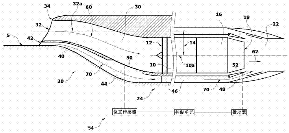
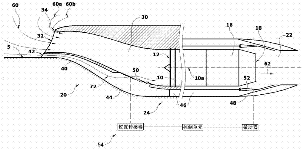
[0014] The stealth air intake system 20 according to an implementation example of the present invention consists of a main air inlet 30, an air intake bypass 40, an air collection chamber 44, an air path 46, an exhaust bypass 48, an air intake controller 50 and an exhaust The controller 54 is composed. The main intake 30 interfaces with the engine 10 at the engine inlet 12 . Engine bleed air 60 enters the main intake 30 from the main intake 32 and then enters the engine 10 via the engine intake 12 . There is an eccentricity 14 between the central line 32a of the inlet port and the engine axis 10a, and the main inlet port 30 is designed into a curved "S" shape, which can block the engine inlet 12 and nearby engine parts, such as the fan, and reduce the intake. Increase the radar scattering area of ​​the air intake system and improve the stealth of the air in...


PUM


Abstract

The invention relates to an air intake system which is used in an aircraft, and particularly relates to an invisible air intake system. A total main air intake channel of the invisible air intake system is designed into a bent S-like shape; an air intake bypass, an air accumulation cabin, an air path and an exhaust bypass are connected in sequence so as to form into an auxiliary air flow path; an air intake controller is installed on the air accumulation cabin; an exhaust valve is positioned at an outlet of the exhaust valve at the rear part of the auxiliary air flow path; when the air intake controller is at the opened state, the exhaust valve is at the closed state; and when the air intake controller is at the closed state, the exhaust valve is at the opened state. With the adoption of the air intake system, the influence of a boundary layer generated by a wing / body to an engine, and the requirements of the engine on the quantity and the quality of the air intake at different velocities / different engine states are met; and meanwhile, with the adoption of the air intake system, openings in the surface of the wing / body can be reduced with good invisibility performance.

Description

technical field [0001] The present invention relates to air intake systems for use on aircraft. More specifically, it relates to a stealth air intake system. Background technique [0002] Currently, most aircraft are powered by jet engines. During the flight of the aircraft, the air reaches the engine inlet through the air intake system of the aircraft, and then the air is compressed by one or more sets of compressors in the engine, mixed with fuel in the combustion chamber, and burned to form a high-temperature and high-pressure mixed gas. After passing through components such as turbines, it is finally discharged through the exhaust system to generate power to propel the aircraft forward. In order to ensure the stable operation of the jet engine and keep it in its best operating state, it is often necessary to design an air intake system for the corresponding engine in aircraft design. The main design goal of an air intake system on an aircraft is to capture the free fl...

Claims


Application Information

Patent Timeline
Patent Type & Authority Applications(China)
IPC IPC(8): B64D33/02
Inventor 方力王家启艾俊强李青
Owner XIAN AIRCRAFT DESIGN INST OF AVIATION IND OF CHINA
Why Eureka
Try Eureka