Auxiliary braking device of cordless elevator and control method thereof

A technology of auxiliary braking and electronic control unit, which is applied in the direction of transportation, packaging, elevators, etc., can solve the problems of elevator danger, increase of elevators, increase of cost of effective area of ​​buildings, etc., and achieve high-speed braking performance and low energy consumption Effect

Active Publication Date: 2013-02-13
梁山旭日精工机械制造有限公司
View PDF7 Cites 13 Cited by
  • Summary
  • Abstract
  • Description
  • Claims
  • Application Information

AI Technical Summary

Problems solved by technology

Common vertical transportation systems include rope traction elevators and linear motor drive elevators. Among them, rope traction elevators use clamp-type brake protection when a rope breakage accident occurs, and the bridge is stopped by clamping the rails by spring action. There are still two disadvantages in the rope traction elevator: 1. One elevator shaft can only run one bridge compartment. If you want to shorten the waiting time for the elevator, you will increase the number of elevators, which will inevitably reduce the effective area of ​​the building and increase Cost: 2. For some super high-rise buildings, in order to ensure the safety performance, the wire rope of the traction elevator must become longer and thicker, and the power of the motor needs to be increased
[0003] The Chinese patent announcement number is CN 2545174Y, titled "elevator driven by a cylindrical lin...

Method used


Image

  • Auxiliary braking device of cordless elevator and control method thereof
  • Auxiliary braking device of cordless elevator and control method thereof
  • Auxiliary braking device of cordless elevator and control method thereof

Examples


Embodiment Construction

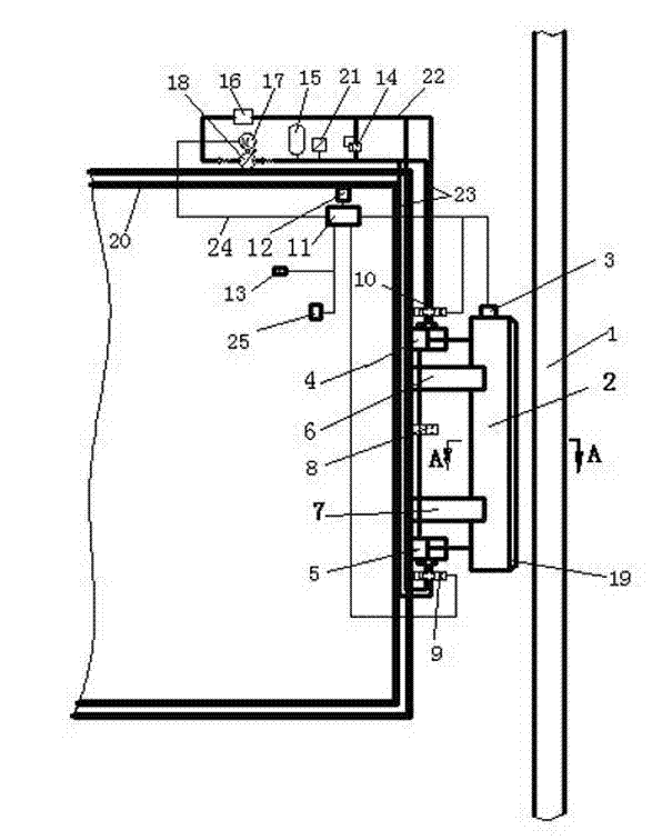
[0018] Such as figure 1 , the present invention includes a linear permanent magnet brake, a hydraulic energy supply system, an electronic control system and a rail 1.

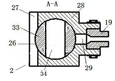
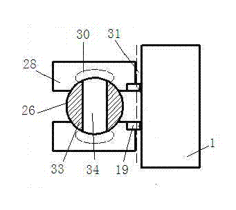
[0019] Wherein the linear permanent magnet brake comprises a brake body 2, a brake shoe 19, force transmission guide pillars 6 and 7, and a rotating mechanism 3. The rail 1 is vertically fixed on the shaft, and there are brake body 2 and brake shoes 19 between the rail 1 and the bridge compartment 20. The brake shoes 19 are fixedly installed on the brake body 2, and the brake shoes 19 face the rail 1 and are parallel to the rail 1. layout. The bridge compartment 20 and the gate body 2 are connected by two force transmission guide columns 6 and 7, the two force transmission guide columns 6 and 7 are arranged in parallel up and down, and one end of the two force transmission guide columns 6 and 7 is fixedly connected to the bridge compartment 20 The side is fixed and the other end is slidingly connected to the ...


PUM


Abstract

The invention discloses an auxiliary braking device of a cordless elevator and a control method thereof. A break body is composed of a magnetic shaft, a magnetic insulation front cover, a rear baffle and two lateral walls and encircled into a hollow structure with a cylindrical middle, and the magnetic shaft is arranged in the hollow structure and can rotate in the hollow structure; and the magnetic shaft is cylindrical and formed by two permanent magnets and a magnetic insulation interlayer which is arranged in the middle and fixedly connected with the two permanent magnets, magnetic pole directions of two permanent magnets in a same radial direction are identical, and one end of the magnetic shaft is fixedly connected with a rotating mechanism which is connected with an electronic control unit. During emergency braking, the electronic control unit controls a break boot to be close to a rail, and non-contact vortex braking force is generated between the break boot and the rail; the electronic control unit controls the rotating mechanism to rotate, and magnetic pole attraction is produced between the break boot and the rail, so that the break boot is absorbed on the rail, and friction braking force is generated; and the problem that sufficient braking force cannot be provided under the condition that emergency braking happens to a prior cordless elevator is solved.

Description

technical field [0001] The invention relates to a cordless elevator, in particular to a braking device for the cordless elevator. Background technique [0002] With the further improvement of the degree of urbanization in our country, the demand for high-rise and super high-rise buildings is increasing. In these high-rise buildings, the vertical transportation system plays a very important role. Common vertical transportation systems include rope traction elevators and linear motor drive elevators. Among them, rope traction elevators use clamp-type brake protection when a rope breakage accident occurs, and the bridge is stopped by clamping the rails by spring action. There are still two disadvantages in the rope traction elevator: 1. One elevator shaft can only run one bridge compartment. If you want to shorten the waiting time for the elevator, you will increase the number of elevators, which will inevitably reduce the effective area of ​​the building and increase Cost: 2...

Claims


Application Information

Patent Timeline
IPC IPC(8): B66B5/18
Inventor 胡东海何仁
Owner 梁山旭日精工机械制造有限公司
Why Eureka
Try Eureka