

Bidirectional noncontact type cooling dynamic sealing method for two-grade liquid ring pump
A non-contact, liquid ring pump technology, used in liquid fuel engines, components of pumping devices for elastic fluids, pumps, etc. Impeller hub thermal deformation, affecting the stability of liquid ring pump operation, etc., to prevent gas backflow, solve wear, and prevent thermal deformation.
- Summary
- Abstract
- Description
- Claims
- Application Information
AI Technical Summary
Problems solved by technology
Method used
Image

Examples
Embodiment
[0046] The present invention is an improvement on the basis of the prior art, and the newly added parts are all realized by using conventional machining techniques for common machining materials.
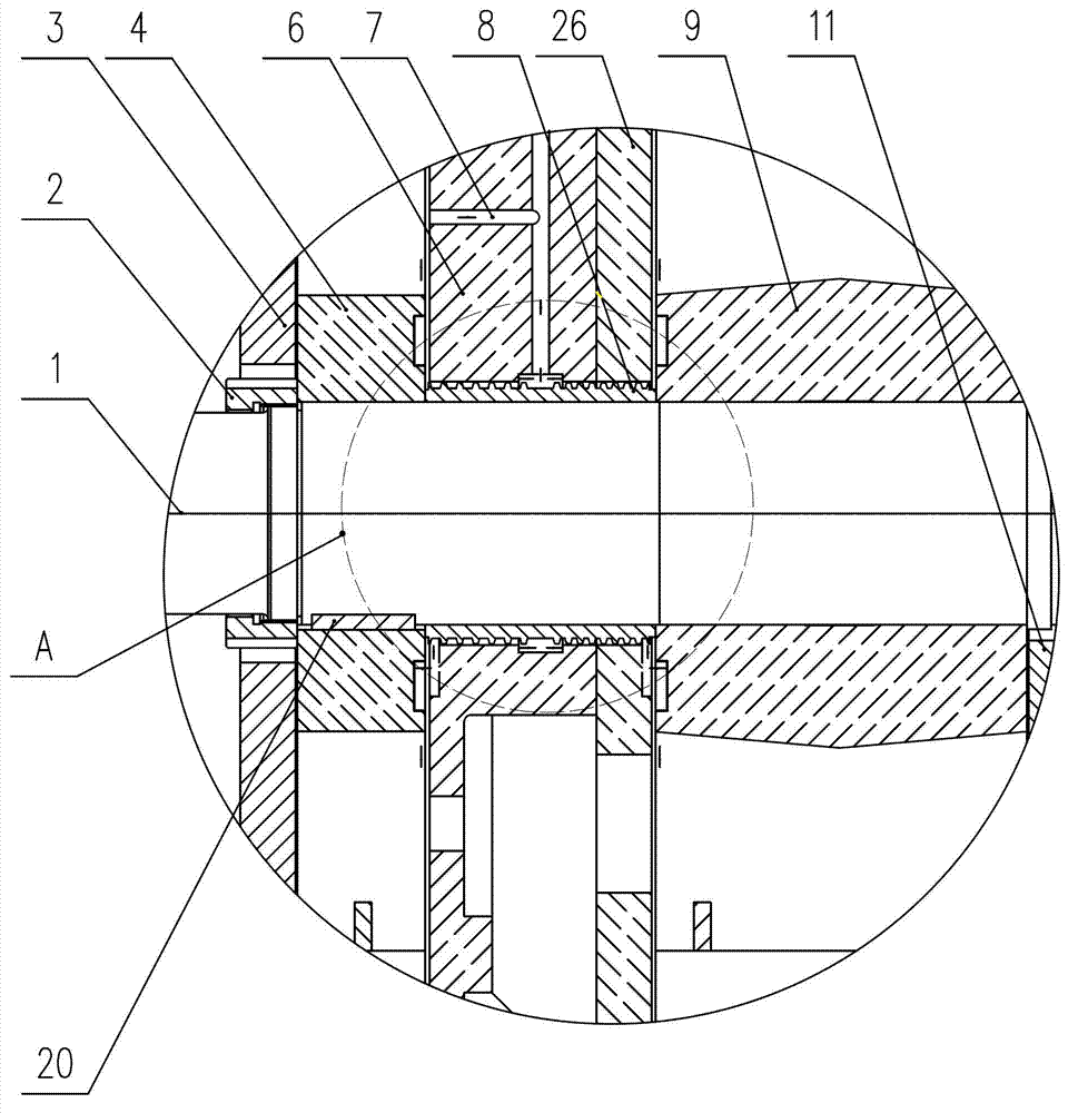
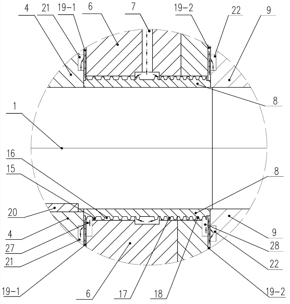
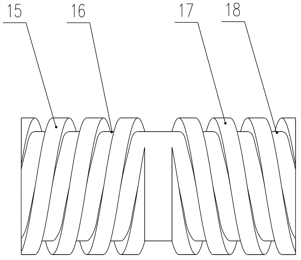
[0047] Its outstanding invention point is to break through the stylized thinking of the existing technology and find another way; a two-way spiral liquid supply mechanism is set between the rotating component and the stationary component of the two-stage liquid ring pump-the combination of the middle wall component, and the non-contact dynamic seal is adopted. ; The sealing structure between the intermediate wall assembly 6 and the liquid ring pump shaft 1 is simplified, a hydraulic seal is realized, and gas backflow between the high and low pressure chambers is effectively prevented. In addition, the cooling of the hub of the impeller of the high and low pressure chamber is realized during the circulation of the sealing liquid, which effectively prevents the thermal deformation of t...
PUM
 Abstract
Description
Claims
Application Information