Liquid cooling narrow-face copper plate for metal continuous casting crystallizer

A continuous casting crystallizer and narrow-faced copper plate technology, which is applied in the field of metal solidification and continuous casting, can solve the problems of unspecified side chamfer cooling mode, unfavorable product cooling consistency, and cooling surface affecting cooling effect, etc., to achieve Solve the cracking of corners, avoid thermal deformation, and prolong the service life

Inactive Publication Date: 2015-12-02
XIXIA LONGCHENG SPECIAL MATERIALS CO LTD
View PDF16 Cites 0 Cited by
  • Summary
  • Abstract
  • Description
  • Claims
  • Application Information

AI Technical Summary

Problems solved by technology

The patent does not point out the cooling method of the side chamfer, which is not conducive to the consistency of product cooling on a horizontal plane
The patent of CN201744629Y discloses a narrow-sided copper plate of a combined crystallizer for continuous casting. Although it is equipped with a relatively comprehensive cooling tank, the small cooling surface will inevitably affect the cooling effect and cause poor heat conduction.

Method used


Image

  • Liquid cooling narrow-face copper plate for metal continuous casting crystallizer
  • Liquid cooling narrow-face copper plate for metal continuous casting crystallizer
  • Liquid cooling narrow-face copper plate for metal continuous casting crystallizer

Examples


Embodiment 1

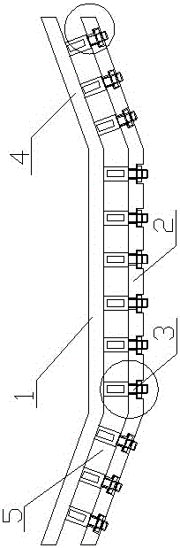
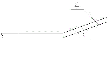
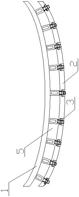
[0039] A metal continuous casting crystallizer liquid-cooled narrow-sided copper plate, comprising a working copper plate 1 whose back is connected to a back plate 2 through a connecting piece 3, the side of the working copper plate 1 is bent to the upper part of the working surface of the working copper plate to form a chamfered surface 4. A coolant gap 5 is formed between the connector 3 and the back plate 2 through the protrusions provided thereon.

[0040] The angle α between the chamfering surface 4 and the horizontal plane of the working copper plate is 20°.

[0041] The starting end of the chamfered surface 4 is 1 / 2 of the distance from the center of the working copper plate 1 to the two sides.

[0042] Said connector is provided with a cylindrical boss 33 on the back of said working copper plate 1 , said cylindrical boss 33 is designed integrally with said working copper plate 1 , and said cylindrical boss 33 is provided with a screw thread 35 .

[0043] The protrusio...

Embodiment 2

[0047] It differs from Embodiment 1 in that:

[0048] The angle α between the chamfered surface and the horizontal plane of the 4 working copper plates is 25°.

[0049] The 4 starting ends of the chamfered surface are 2 / 3 of the distance from the center of the working copper plate to the two sides.

[0050] Said connector is provided with a cylindrical boss 33 on the back of said working copper plate 1 , said cylindrical boss 33 is designed integrally with said working copper plate 1 , and said cylindrical boss 33 is provided with a screw thread 35 .

[0051] The protrusion of the connector 3 is a cylinder 32b sleeved on the cylindrical boss.

[0052] A guide hole is provided on the cylinder 32b.

[0053] Arranging the diversion hole on the cylinder can make the coolant flow therein, take away the heat on the cylindrical boss and the cylinder, speed up the heat dissipation surface, and reduce the resistance of the coolant.

Embodiment 3

[0055] The difference from the second embodiment is that the angle α between the chamfered surface 4 and the horizontal plane of the working copper plate is 30°.

[0056] The starting end of the chamfered surface 4 is 3 / 5 of the distance from the center of the working copper plate to the two sides.

[0057] Said connector is provided with a cylindrical boss 33 on the back of said working copper plate 1 , said cylindrical boss 33 is designed integrally with said working copper plate 1 , and said cylindrical boss 33 is provided with a screw thread 35 .

[0058] The protrusion of the connector 3 is a cylinder 32b sleeved on the cylindrical boss.

[0059] A guide hole is provided on the cylinder 32b.

[0060] A circular hole 34 is arranged radially at the upper thread of the cylindrical boss 33 .

[0061] An assembly hole 37 communicating with the side of the backboard is provided on the inner wall of the hole on the side of the backboard 2 .

[0062] A rigid tension rope 36 is...


PUM


Abstract

The invention discloses a liquid cooling narrow-face copper plate for a metal continuous casting crystallizer. The liquid cooling narrow-face copper plate for the metal continuous casting crystallizer comprises a work copper plate, and the back face of the work copper plate is connected with a back plate through connecting pieces. The sides of the work copper plate bend toward the upper portion of the work face of the work copper plate to form chamfer angle faces. Coolant spaces are formed between the connecting pieces and the back plate through protrusions arranged on the connecting pieces. According to the liquid cooling narrow-face copper plate, a sealing wall can be arranged on the back plate during machining, so that sealing of cooling liquid is guaranteed; the sealing wall and a wide plate of the crystallizer can also form a ring-shaped water channel directly, so that the best heat conduction effect is obtained under the circumstance that stabilization of the crystallizer is guaranteed; the partial thermal deformation of the copper plate is avoided; the heat conduction effect is guaranteed, and the quality of steel billets is improved; the service life of the copper plate is prolonged.

Description

technical field [0001] The invention relates to the technical field of metal solidification and continuous casting, in particular to a liquid-cooled narrow-faced copper plate of a metal continuous casting crystallizer. Background technique [0002] With the development of metallurgical technology in the world, modern continuous casting technology continues to improve, and the types of castable steel continue to expand. Some high-alloy, high-quality, and high-crack-sensitive steel types have been continuously produced in the continuous casting production process of large iron and steel enterprises; this One of the main technological advances is the development of large-section slab continuous casting technology; the development of large-section slab continuous casting technology increases the compression ratio of steel and improves the quality of steel products; The adverse effect is: in the continuous casting process, due to the large volume of the casting slab, when it chan...

Claims


Application Information

Patent Timeline
Patent Type & Authority Applications(China)
IPC IPC(8): B22D11/059
Inventor 朱书成赵家亮黄国团廖春谊马超
Owner XIXIA LONGCHENG SPECIAL MATERIALS CO LTD
Why Eureka
Try Eureka