Combined heat exchanger

A heat exchanger and combined technology, which is applied in the field of heat exchangers of electrical appliances, can solve the problems of frosting and icing on the surface of the evaporator, difficulty in drainage of condensed water, etc., and achieve the effect of expanding the scope of application

Inactive Publication Date: 2013-02-13
GREE ELECTRIC APPLIANCES INC OF ZHUHAI
View PDF5 Cites 10 Cited by
  • Summary
  • Abstract
  • Description
  • Claims
  • Application Information

AI Technical Summary

Problems solved by technology

If fins are added to the heat pipe to enhance heat exchange, since the heat exchange tubes need to be arranged vertically, the fins will be arranged horizontally, which will cause condensed water in the air to condense on the fin

Method used


Image

  • Combined heat exchanger
  • Combined heat exchanger
  • Combined heat exchanger

Examples


Example Embodiment

[0024] The embodiments of the present invention will be described in detail below with reference to the accompanying drawings, but the present invention can be implemented in a variety of different ways defined and covered by the claims.

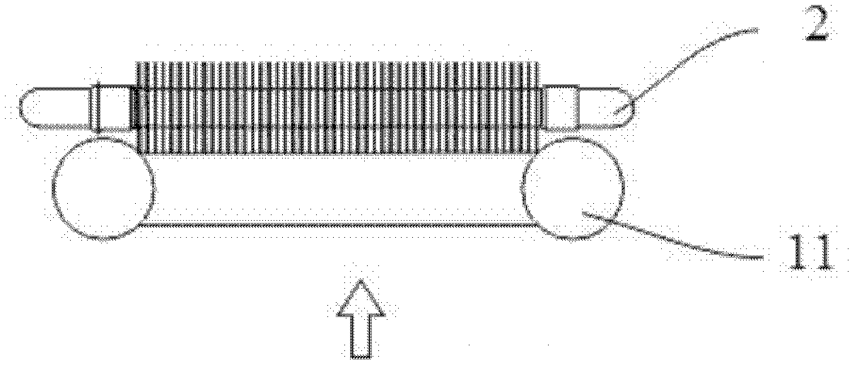
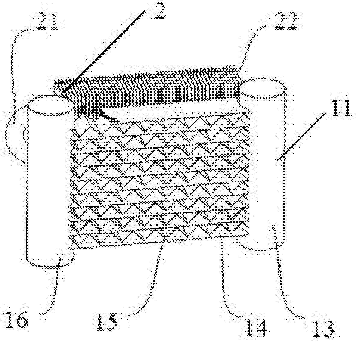
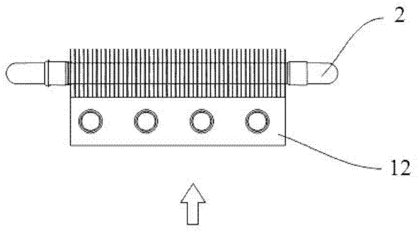
[0025] The combined heat exchanger of the present invention combines two heat exchangers. Specifically, a microchannel heat exchanger or a heat pipe heat exchanger or a similar heat exchanger of the type difficult to automatically drain is placed on the bottom of the combined heat exchanger. Windward side; the heat exchanger with longitudinal fins is placed on the leeward side of the combined heat exchanger. Preferably, the heat exchanger can use a hydrophilic material as the longitudinal fins, and the longitudinal fins are in close contact On the windward surface of the micro-channel heat exchanger or heat pipe heat exchanger, these longitudinal fins form a channel for guiding the condensate accumulated on the surface of the micro-channel heat ...


PUM


Abstract

The invention provides a combined heat exchanger, which comprises a first heat exchanger and a second heat exchanger, wherein the second heat exchanger is provided with longitudinal fins and is combined with the first heat exchanger; and the longitudinal fins are in contact with the surface of the first heat exchanger. The combined heat exchanger has the advantages that the original advantages of a microchannel heat exchanger and a heat pipe heat exchanger or heat exchangers with similar characteristics are reserved by the technical scheme, and the applicable range of the heat exchangers is enlarged by overcoming the defect of difficulty in discharge of aggregated condensate water.

Description

technical field [0001] The invention relates to the field of heat exchangers for air conditioners and other electrical appliances, in particular to a combined heat exchanger. Background technique [0002] The microchannel (parallel flow) heat exchanger has the advantages of high heat transfer coefficient, compact structure, low cost, and small amount of refrigerant perfusion. Its application range is gradually expanding. Flat heat exchange tubes (harmonica tubes) between headers and fins installed between the flat heat exchange tubes. Since the microchannel heat exchanger is welded as a whole, hydrophilic aluminum foil cannot be used for the fins, and the welded aluminum foil is prone to bead-like condensation and form a "water bridge". Moreover, the structure of the flat heat exchange tube (harmonica tube) itself is a horizontal plate. Due to the tension of the water, if there is condensed water, it will not be able to be drained smoothly in time, which limits its scope of...

Claims


Application Information

Patent Timeline
IPC IPC(8): F25B39/00F25D21/14
Inventor 林海佳肖洪海赵鹏张杰
Owner GREE ELECTRIC APPLIANCES INC OF ZHUHAI
Why Eureka
Try Eureka