Heat exchanger structure

A technology of heat exchangers and heat exchange tubes, which is applied to the types of heat exchangers, heat exchanger shells, indirect heat exchangers, etc. The heat exchange efficiency of the heat exchanger and other issues can be improved to improve the heat exchange effect, reduce the possibility of equipment blockage and failure, and achieve good purging effect

Inactive Publication Date: 2013-02-13
ZHENHAI PETROCHEM JIANAN ENG
View PDF9 Cites 10 Cited by
  • Summary
  • Abstract
  • Description
  • Claims
  • Application Information

AI Technical Summary

Problems solved by technology

Uneven mixing will not only cause the fluid to drift, but also affect the heat transfer efficiency of the heat exchanger. The heat transfer effect cannot meet the process requirements, which will bring hidden dangers to the long-term stable operation of the equipment.
At the same time, in order to improve the heat exchange efficiency of the equipment, the arrangement of heat exchange components such as tube bundles is relatively close, and the spacing is often small, which will also cause uneven mixing of the shell-side fluid of the heat exchanger and affect the heat exchange efficiency.

Method used


Image

  • Heat exchanger structure
  • Heat exchanger structure

Examples


Embodiment Construction

[0015] The present invention will be further described in detail below in conjunction with the accompanying drawings and embodiments.

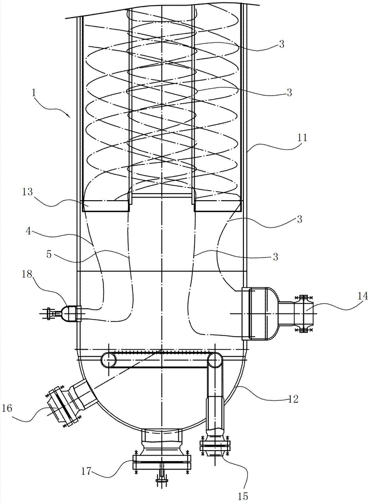
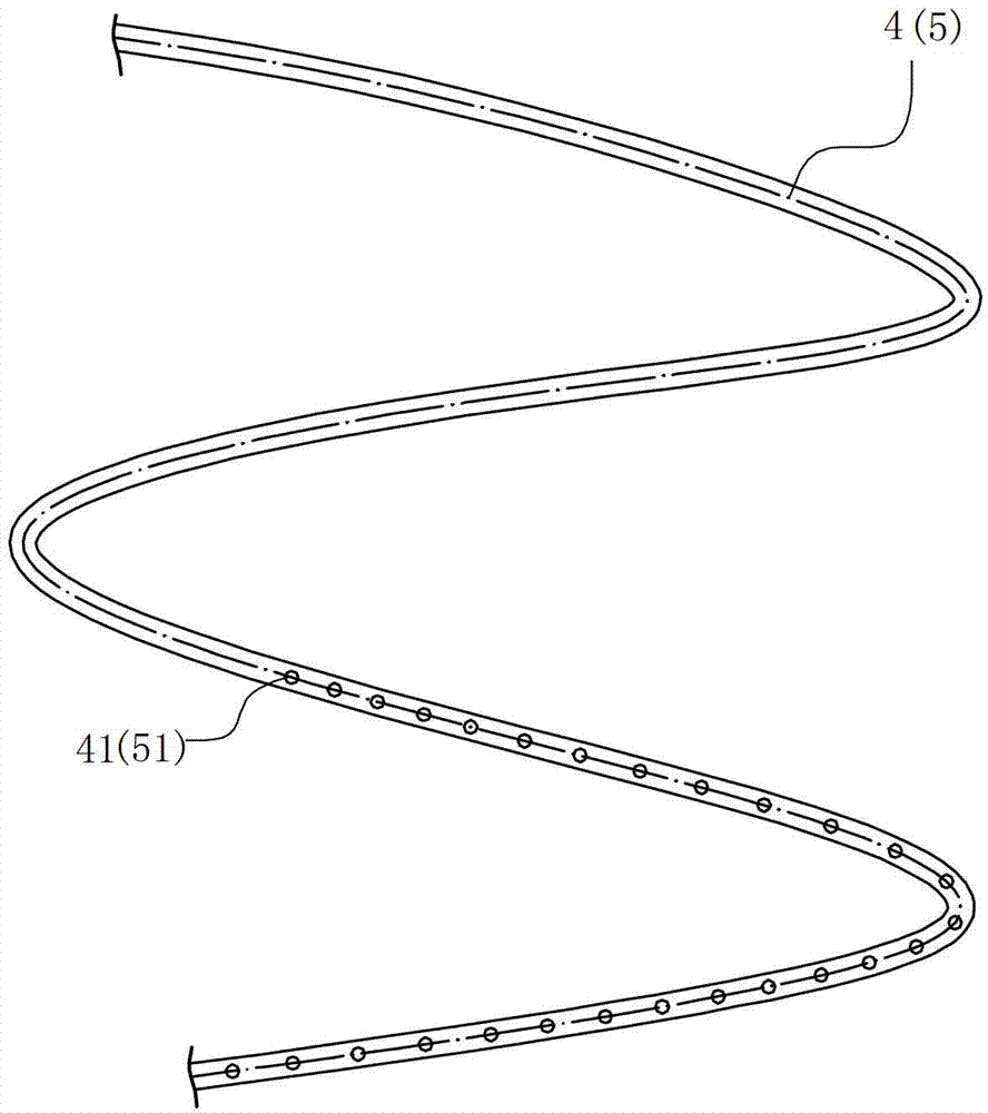
[0016] Such as figure 1 with figure 2 As shown, this embodiment takes a vertical heat exchanger as an example for description, and the technology of the present invention is also applicable to a horizontal heat exchanger. The heat exchanger structure includes:

[0017] The casing 1 is a closed structure, including an upright cylinder 11, an upper head (not shown in the figure) and a lower head 12 arranged at both ends of the cylinder, and the two ends of the cylinder inside the casing are also provided with parallel The first tube sheet (not shown in the figure) and the second tube sheet 13, the shell is provided with a tube side inlet (not shown in the figure), a tube side outlet 14, a shell side gas phase inlet 15, a shell side liquid phase Inlet 16, shell side outlet (not shown in the figure) and condensate discharge port 17, which can ...


PUM


Abstract

The invention relates to a heat exchanger structure which comprises a closed casing and multiple heat exchange tubes arranged in the casing. Two ends of each heat exchange tube are respectively limited on a first tube plate and a second tube plate, and the first tube plate and the second tube plate are parallelly arranged in the casing. The heat exchanger structure is characterized in that the heat exchange tubes form multiple layers of helix tubes which are sequentially arranged in a sleeved mode at intervals, first air tubes are further and spirally coiled in each layer of helix tubes in the same direction, a plurality of first air holes are distributed on tube walls of the first air tubes facing the bottom of the casing, and air inlets and air outlets of the first air tubes are communicated with an outside air source. Compared with the prior art, the first air tubes are arranged in the casing, so that the all-around disturbance can be internally performed to a fluid in the casing side, fluid media can be mixed and be continuously even gradually even under the conditions that the fluid media are dirty and sticky and the tube spacing and the layer spacing are tight, the fluid deposition in the casing is effectively avoided, the heat transfer efficiency is improved, the heat exchange effect is improved, and cleaning, blowing, sweeping and maintenance of a device are facilitated.

Description

technical field [0001] The invention relates to the field of chemical equipment, in particular to a heat exchanger structure. Background technique [0002] Under the general background of energy saving and emission reduction and crude oil degradation, the raw material medium encountered by heat exchangers and other cold exchange equipment is generally dirty and sticky. When flowing through the heat exchanger, the dirty and sticky medium will not only deposit on the Above and outside the inner wall of the heat exchanger, it is important to affect the fluidity of the medium in the heat exchanger and the uniformity of the flow field distribution; if the shell side medium of the heat exchanger is gas and liquid two-phase The nozzles enter the shell side of the heat exchanger respectively, so the medium with high viscosity will inevitably affect the degree of uniform mixing of the two-phase medium. Uneven mixing will not only cause the fluid to drift, but also affect the heat tr...

Claims


Application Information

Patent Timeline
Patent Type & Authority Applications(China)
IPC IPC(8): F28D7/02F28F9/02
CPCF28D7/024F28F19/00F28G9/00
Inventor 张贤安王健良胡兴苗刘利江吴力俊
Owner ZHENHAI PETROCHEM JIANAN ENG
Why Eureka
Try Eureka