Moisture two-phase flow measuring device with annular chamber gas-liquid separation pressure measuring device

A flow measurement device and gas-liquid isolation technology, which is applied to the volume/mass flow generated by mechanical effects, and the detection of fluid flow by measuring differential pressure, which can solve the problems of low efficiency of gas-liquid isolation, long dynamic balance process, and low signal-to-noise ratio To achieve the effect of speeding up the gas-liquid dynamic equilibrium process, high gas-liquid isolation efficiency, and improving safety and life

Active Publication Date: 2013-02-13
成都厚和精测科技有限公司
View PDF5 Cites 6 Cited by
  • Summary
  • Abstract
  • Description
  • Claims
  • Application Information

AI Technical Summary

Problems solved by technology

Practice has proved that this design has the following disadvantages: (1) The single-point pressure measurement method is adopted, which leads to unsatisfactory stability of pressure measurement information in wet gas and low signal-to-noise ratio (2) There is only one pressure measurement hole on the tube wall of the measurement device, The gas-liquid dynamic balance process of the isolation tank is relatively long, and the gas-liquid isolation efficiency is low; (3) The main body o

Method used


Image

  • Moisture two-phase flow measuring device with annular chamber gas-liquid separation pressure measuring device
  • Moisture two-phase flow measuring device with annular chamber gas-liquid separation pressure measuring device

Examples


Embodiment Construction

[0013] The present invention will be described in further detail below with reference to the accompanying drawings.

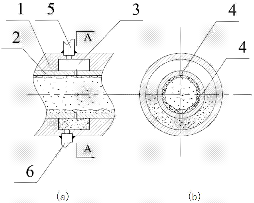
[0014] The present invention is an annular chamber gas-liquid isolation pressure taker used in the wet gas flow measuring device, the structural diagram is as follows figure 1 shown. The moisture measuring device may be a cone throttling device, a Venturi throttling device, a nozzle and orifice throttling device throttling device, etc. for moisture measurement.

[0015] In the present invention, a middle ring chamber gas-liquid isolation pressure taker 1 is arranged at each pressure take place on the measuring pipeline 2 of the wet gas two-phase flow measuring device. Four pressure-taking holes 4 are set on the same plane where the pressure-taking place of the measuring pipeline 2 is perpendicular to the axis, two at the maximum diameter in the horizontal direction, two at the maximum diameter in the vertical direction, and four pressure-taking holes 4 An ann...


PUM


Abstract

The invention belongs to the field of a moisture gas-liquid two-phase flow measuring technology and relates to a moisture two-phase flow measuring device with an annular chamber gas-liquid separation pressure measuring device, comprising a measuring pipeline, wherein a pipe wall of each pressure measuring position of the measuring pipeline, which is located on the same plane vertical with a axis, is provided with four inner pressure measuring holes; the two of the four inner pressure measuring holes are formed at the maximum diameter position in a horizontal direction of the pipe wall, and the other two of the four inner pressure measuring holes are formed at the maximum diameter position in a vertical direction of the pipe wall; an annular chamber structure is fixedly arranged on the peripheries of the four inner pressure measuring holes; the annular chamber and a measuring pipeline body are coaxial and are fixedly arranged on the outer wall of each pressure measuring position of the measuring pipeline body so as to form a gas-liquid separation chamber with a certain capacity space; a pressure leading opening which is abutted with an outer pressure leading pipe is formed above the vertical axis of the chamber; and a dirt discharging opening which is abutted with an outer dirt discharging pipe is formed below the vertical axis of the chamber. The moisture two-phase flow measuring device has the advantages that the structure is simple, the dependence on a large-sized gas-liquid separator is free, pressure measuring precision is high, pressure measurement is not influenced by a liquid phase, and the implementation is convenient.

Description

technical field [0001] The invention belongs to the technical field of two-phase flow measurement and relates to a wet gas two-phase flow measurement device. Background technique [0002] Moisture, as a special form of gas-liquid two-phase flow, exists widely in nature and industry. When gas and liquid flow alone, the flow laws are basically the same, and both obey the basic mass conservation and energy conservation equations, and the mathematical models are basically similar, but when they coexist and flow at the same time, due to the large difference in the medium characteristics of the two-phase fluid Differences, such as friction coefficient, fluid density and viscosity and other physical parameters are different, and the two-phase fluids interact and influence each other, making the gas-liquid two-phase flow show more complex characteristics compared with single-phase flow , many criterion relations and analytical methods in single-phase flow cannot be directly applied...

Claims


Application Information

Patent Timeline
IPC IPC(8): G01F1/36
Inventor 徐英张涛张强
Owner 成都厚和精测科技有限公司
Why Eureka
Try Eureka