
Onboard LED automatic testing method

An automatic testing, onboard technology, applied in the direction of lamp testing, testing optical performance, etc., can solve the problems of reducing the efficiency of inspection, increasing the cost of LED inspection, and improving the complexity and difficulty of inspection work, so as to improve the efficiency and shorten the shutter time. , The effect of simplifying the testing process

Inactive Publication Date: 2013-02-13
SHANGHAI GONGJIN COMM TECH
View PDF6 Cites 11 Cited by
  • Summary
  • Abstract
  • Description
  • Claims
  • Application Information

AI Technical Summary

Problems solved by technology

But the problem is that this test equipment must use a detection chamber to ensure that the detection process is not affected by external light sources in order to achieve the expected detection effect
However, in order to realize the inspection of the quality of LED equipment, the inspection must be carried out after the LED assembly work is completed. Placing the circuit boards and other boards on which the LEDs are fixed together in a inspection chamber obviously increases the complexity and difficulty of the inspection work. , which reduces the detection efficiency
On the other hand, corresponding to the LEDs installed on different boards, different detection chambers are required to ensure the detection effect under the applicable conditions, which obviously increases the cost of LED detection

Method used


Image

  • Onboard LED automatic testing method
  • Onboard LED automatic testing method

Examples


Embodiment approach

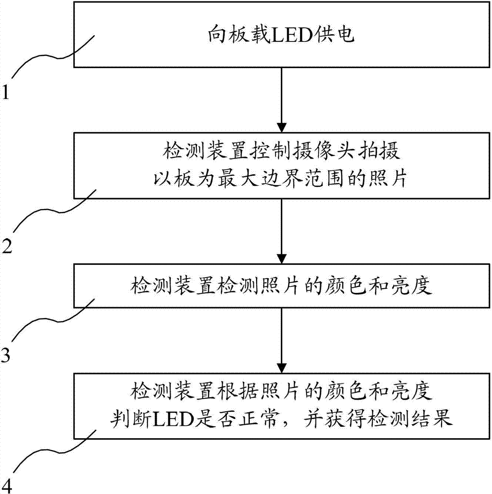
[0025] In one embodiment, the method comprises the steps of:

[0026] (1) supplying power to the on-board LED, and the on-board LED is arranged on a circuit board or panel;

[0027] (2) The detection device controls the camera to take photos with the board as the maximum boundary range;

[0028] (3) The detection device detects the color and brightness of the photo;

[0029] (4) The detection device judges whether the LED is normal according to the color and brightness of the photo, and obtains the detection result.

[0030] In a preferred embodiment, the power supply to the onboard LED described in step (1) is specifically to supply power to the onboard LED, so that when the background brightness is 20-30, the LED to be detected reaches 90-100 Brightness range (LED brightness RGB three colors are 0~255, corresponding brightness range is 0~100). And the shortest exposure time for the camera to take photos with the board as the maximum boundary range is 1 / 1500 second, and th...


PUM


Abstract

The invention relates to an onboard LED automatic testing method, and belongs to the technical field of quality control for electronic products. In the method, detecting equipment controls a camera to only photograph within the maximum boundary of a board where the LED is located, further the color and luminance of the picture can be tested to obtain the testing result of the LED, so that the influence of light rays of the ambient environment on the testing is avoided as far as possible, the testing requirement can be met without adopting a testing accommodating chamber, the testing procedure is greatly simplified, the testing efficiency is improved, further, the shutter time of the camera can be shortened through improving the luminance of the LED, the luminance of the LED and the luminance of the background can be distinguished better, and the testing accuracy is improved. The onboard LED automatic testing method provided by the invention is low in cost and has a wider application range.

Description

technical field [0001] The invention relates to the technical field of electronic product quality monitoring, in particular to the technical field of LED detection, in particular to an automatic test method for onboard LEDs. Background technique [0002] In industrial production, especially in the electronics industry, the number of LEDs in a product is usually large. After installing the LED on the circuit board or panel, it is necessary to test whether the LED installation is normal. The commonly used test method is to rely on human eye recognition, which makes the test results prone to errors and the test efficiency is low. Therefore, only by using effective automated testing instead of traditional manual testing, can we meet the needs of the increasingly large-scale production of electronic products. [0003] In the prior art, an ordinary camera is usually used together with an image recognition device to realize large-scale automatic detection of LEDs. Such as the li...

Claims


Application Information

Patent Timeline
Patent Type & Authority Applications(China)
IPC IPC(8): G01M11/02G01R31/44
Inventor 黄亮王浩徐荣鑫
Owner SHANGHAI GONGJIN COMM TECH
Learn More