Infrared image automatic fault identifying method for high-voltage equipment

An infrared image, fault identification technology, applied in fault location, radiation pyrometry, instruments, etc., can solve the problems of difficult sound, false detection or missed detection, and low efficiency of spark discharge.

Active Publication Date: 2013-02-13
MAINTENANCE BRANCH OF STATE GRID CHONGQING ELECTRIC POWER +1
View PDF8 Cites 59 Cited by
  • Summary
  • Abstract
  • Description
  • Claims
  • Application Information

AI Technical Summary

Problems solved by technology

For low-value electrical equipment in operation, especially when there are many pieces of low-value insulators in a string, it is difficult to make a correct judgment
These traditional electrical equipment detection methods are not only labor-intensive, poor in safety, and low in efficiency, but also the sound of spar

Method used


Image

  • Infrared image automatic fault identifying method for high-voltage equipment
  • Infrared image automatic fault identifying method for high-voltage equipment
  • Infrared image automatic fault identifying method for high-voltage equipment

Examples


Embodiment Construction

[0040] The preferred embodiments of the present invention will be described in detail below in conjunction with the accompanying drawings; it should be understood that the preferred embodiments are only for illustrating the present invention, rather than limiting the protection scope of the present invention.

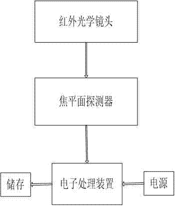
[0041] Figure 1 is a schematic structural diagram of an infrared thermal imager provided in an embodiment of the present invention. The infrared thermal imager used in an embodiment of the present invention to obtain imaging images includes an infrared optical lens, a focal plane detector, and an electronic processing device connected in sequence. The electronic processing device is respectively connected to a power supply and a storage device. The measurement principle of the infrared thermal imager is as follows: infrared thermal imaging technology is a non-contact diagnostic technology for scanning and imaging thermal radiation of objects. The infrared thermal image o...


PUM


Abstract

The invention discloses an infrared image automatic fault identifying method for high-voltage equipment. Firstly, electric equipment in need of detection is selected and a temperature image of the electric equipment is obtained; secondly, a heating point, heating a point temperature T1 and a normal phase temperature T2 of the electric equipment are obtained through processing of the temperature image; thirdly, a relative temperature is calculated in combination with an environment reference temperature T0 to judge a running condition and fault information of the electric equipment. In the infrared image automatic fault identifying method for the high-voltage equipment, the running condition and the fault information of the electric equipment on a high-voltage transmission wire are monitored on the basis of an infrared image processing technology, a temperature heating abnormal point is detected according to an infrared temperature image processing technology, a heating temperature, a normal temperature, an environment temperature and the relative temperature of an abnormal point are calculated and then the running condition and the fault information of the electric equipment are automatically judged according to a relative temperature difference judging method; in this case, quick on-line detection of the running condition of the electric equipment is realized.

Description

technical field [0001] The invention relates to a high-voltage test equipment, in particular to a high-voltage equipment infrared image automatic fault identification method for detecting the operation status of electrical equipment on a high-voltage transmission line. Background technique [0002] At present, all power supply enterprises basically use spark gap discharge forks and short-circuit forks to manually climb poles and towers to detect the operation status of electrical equipment. These test methods are simple but less accurate. For low-value electrical equipment in operation, especially when there are many pieces of low-value insulators in a string, it is difficult to make a correct judgment. These traditional electrical equipment detection methods are not only labor-intensive, poor in safety, and low in efficiency, but also the sound of spark discharge during detection is easily covered by the noise of the surrounding environment, making it difficult to accurate...

Claims


Application Information

Patent Timeline
IPC IPC(8): G01R31/08G01R31/02G01J5/00
Inventor 魏钢冯中正刘航吴琛邓旭东唐巾鸿李娜
Owner MAINTENANCE BRANCH OF STATE GRID CHONGQING ELECTRIC POWER
Why Eureka
Try Eureka