Method for detecting faults of integrated circuit

An integrated circuit and fault detection technology, applied in the direction of electronic circuit testing, etc., can solve the problems of discount of practical effect, limited number of detectable nodes, noise, etc., and achieve the effect of insensitivity to noise.

Inactive Publication Date: 2013-02-13
UNIV OF ELECTRONICS SCI & TECH OF CHINA
View PDF4 Cites 8 Cited by
  • Summary
  • Abstract
  • Description
  • Claims
  • Application Information

AI Technical Summary

Problems solved by technology
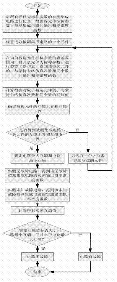
These methods can realize the fault detection of integrated circuits in theory, but due to the limitation of the number of detectable nodes of

Method used


Image

  • Method for detecting faults of integrated circuit
  • Method for detecting faults of integrated circuit
  • Method for detecting faults of integrated circuit

Examples


Embodiment 1

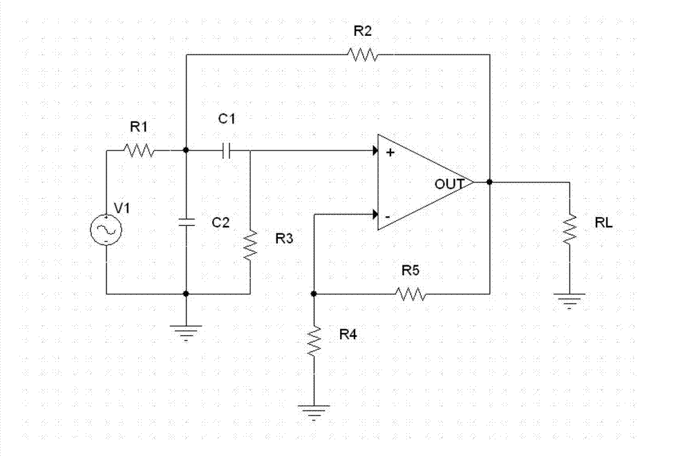
[0070] Such as figure 1 , figure 2 shown. The second-order Sallenkey band-pass filter in the international standard circuit is selected to verify the integrated circuit fault detection method of the present invention. The nominal parameters of each component of the second-order Sallenkey bandpass filter are: R1=5.18 KΩ, R2=1 KΩ, R3=2 KΩ, R4= R5=4 KΩ, RL=10 KΩ, C1=C2=5nF. The tolerance range of each component of the second-order Sallenkey bandpass filter circuit is ±5%; use "↑" and "↓" to represent the positive offset and negative offset of the component parameters of the second-order Sallenkey bandpass filter, respectively. For example, "Rx 10%↑" means that the resistance value of resistor Rx is positively shifted by 10%, such as "Cy 10%↓" means that the capacitance value of capacitor Cy is negatively shifted by 10%. The automatic regression model of the second-order Sallenkey bandpass filter is adopted, and the order of the AR model is 10, that is, q=10. The number of ou...

Embodiment 2

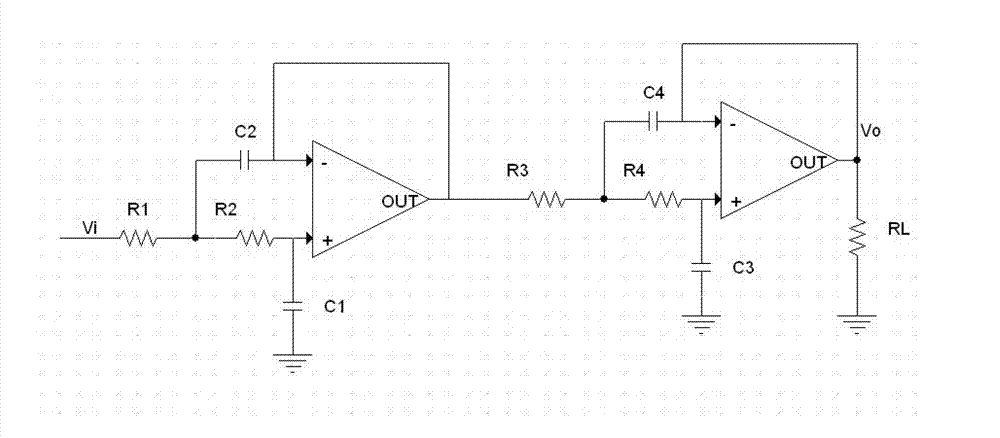
[0086] Such as figure 1 , image 3 shown. The same places as in Embodiment 1 will not be described again, the difference is that a fourth-order low-pass Chebyshev filter in an international standard circuit is selected to verify the method of the present invention. The nominal parameters of each component of the fourth-order low-pass Chebyshev filter are: R1=26.7 KΩ, R2=73 KΩ, R3=11.8 KΩ, R4=67.8 KΩ, RL=10 KΩ, C1=4.7 nF, C2= 10nF, C3=1nF, C4=47nF. The upper bounds and lower bounds of the cross-entropy of each element of the fourth-order low-pass Chebyshev filter within the tolerance range of ±5% are shown in the table below. It can be seen from the table below that the minimum cross-entropy of the circuit of the fourth-order low-pass Chebyshev filter is -0.1596, and the maximum cross-entropy of the circuit is 0.1701.

[0087]

[0088] Put "R1 9%↑", "R3 20%↑", "R1 7%↓", "R3 10%↓", "C2 10%↓", "R1 8%↓", "C1 8%↓" The seven faults are respectively injected into the fourth-o...


PUM


Abstract

The invention discloses a method for detecting faults of an integrated circuit. The method comprises the following steps of: obtaining an output probability density function (of each element) within a nominal parameter tolerance range through Monte Carlo simulation one by one; respectively calculating together with an output probability density function of a tested integrated circuit under each element nominal parameter so as to obtain a mutual entropy value, wherein the maximum value of the mutual entropy value is used as the maximum mutual entropy of the circuit, and the minimum value of the mutual entropy value is used as the minimum mutual entropy of the circuit; subsequently calculating an actual measurement output probability density function of a non-fault tested integrated circuit with an actual measurement output probability density function of an uncertain fault tested integrated circuit so as to obtain an actual measurement mutual entropy value; and finally comparing the actual measurement mutual entropy with the maximum mutual entropy and the minimum mutual entropy of the circuit so as to determine whether the integrated circuit has faults or not. Compared with the prior art, the method has fewer testing nodes and is simple and convenient in testing process, low in testing cost and insensitive to noise.

Description

technical field [0001] The invention belongs to the field of integrated circuit testing, in particular to a fault detection method for integrated circuits. Background technique [0002] Aging, environmental temperature changes and other reasons can cause the parameters of integrated circuit components to deviate from their nominal values. Slight deviations of component parameters can cause the performance of integrated circuits to degrade. However, if the deviation of component parameters exceeds its tolerance range, this large deviation will become the At this time, although the topology of the circuit has not changed, the performance of the circuit may be severely degraded, or even fail. In engineering practice, it is generally considered that the integrated circuit has failed when the actual parameters of the circuit components deviate from their nominal parameters by more than ±5%. Due to the limited testable nodes, the nonlinear characteristics of circuits, and the dif...

Claims


Application Information

Patent Timeline
IPC IPC(8): G01R31/28
Inventor 谢永乐李西峰周启忠毕东杰
Owner UNIV OF ELECTRONICS SCI & TECH OF CHINA
Why Eureka
Try Eureka