
Non-contact power supply system and method for mobile device moving along track

A mobile device and orbital operation technology, applied in electromagnetic wave systems, circuit devices, electrical components, etc., can solve the problems of rigid power supply mode, unfavorable speed increase of mobile devices, high cost, etc. The effect of flexible use

Active Publication Date: 2013-02-13
HUNAN YINHE ATITAN TECH CO LTD
View PDF6 Cites 17 Cited by
  • Summary
  • Abstract
  • Description
  • Claims
  • Application Information

AI Technical Summary

Problems solved by technology

[0006] First of all, in order to ensure the strict contact between the current collector and the current receiving rail, during the operation of the system, a large external force is required to make the current collector press the current receiving rail tightly, which will increase the friction between the two, Limits the acceleration of the mobile device, so it is not conducive to the increase of the speed of the mobile device
[0007] At the same time, due to the long-term friction between the current collector and the current rail, both the current collector and the current rail are subject to wear, and the friction may even damage the mobile device. In severe cases, the entire transportation system cannot operate normally.
In this case, it is necessary to shut down the equipment for inspection and maintenance, resulting in high costs
[0008] In addition, the power supply mode of the whole system is relatively rigid, which is not conducive to flexible control and energy saving

Method used

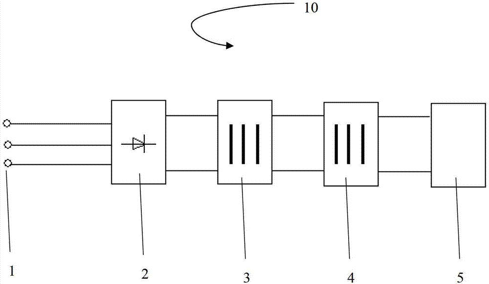

Image

  • Non-contact power supply system and method for mobile device moving along track
  • Non-contact power supply system and method for mobile device moving along track
  • Non-contact power supply system and method for mobile device moving along track

Examples


Embodiment Construction

[0029] The present invention will be further described below in conjunction with accompanying drawing.

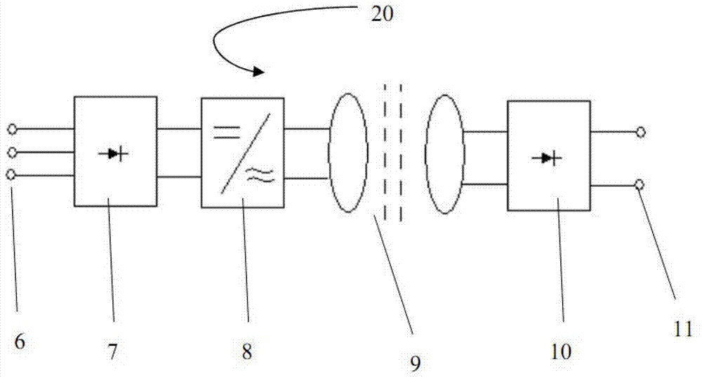
[0030] figure 2 is a contactless power supply system 20 for a mobile device running along a track according to the present invention. Wherein the alternating current 6 provided by the ground power supply first passes through the first rectifier 7 . The first rectifier 7 rectifies and filters the alternating current 6 provided by the ground power supply, and converts it into direct current.

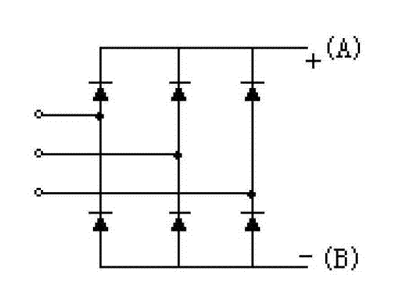
[0031] In one embodiment, the alternating current 6 provided by the ground power supply is three-phase alternating current. The first rectifier 7 is for example image 3 The conventional three-phase diode uncontrolled rectification circuit shown converts three-phase alternating current 6 into direct current. Since those skilled in the art refer to the attached image 3 It is easy to understand the working principle of the first rectifier 7 in this embodiment, and the circuit will ...


PUM


Abstract

The invention relates to a non-contact power supply system for a mobile device moving along a track. The system comprises a first rectifier, an inverter, a transformer and a second rectifier, wherein the first rectifier converts alternating current which is input from the outside into direct current; the inverter converts the direct current which is output by the first rectifier into alternating current; the transformer comprises a primary iron core and a secondary iron core which are separated, a primary winding is wound on the primary iron core, and a secondary winding is wound on the secondary iron core; and the second rectifier is connected with the mobile device, the alternating current which is output by the inverter is input into the primary winding, the sensed alternating current in the secondary winding is converted into direct current through the second rectifier, and then the direct current is provided for the mobile device. The invention also relates to a non-contact power supply device of the mobile device moving along the track. According to the system and the method, the operation is simple, the restriction of speed of the mobile device in the prior is reduced, and energy conservation and safety are achieved.

Description

technical field [0001] The invention relates to a power supply system, in particular to a non-contact power supply system for a mobile device running along a track. [0002] The invention also relates to a contactless power supply method for a mobile device running along a track. Background technique [0003] Subways, light rail trains and maglev trains are all transportation devices that move along the track, and the loading trolleys on the production line are also devices that move along the dedicated production line to transport goods. These devices all need power supply during operation. There are two traditional power supply methods: "drag pigtails" or laying current-receiving rails. The so-called "drag braid" refers to the use of flexible cables to extend the power supply line to the furthest distance required. However, when using this method to supply power, the line loss is serious and the reliability is poor. Laying current receiving rail refers to laying a speci...

Claims


Application Information

Patent Timeline
Patent Type & Authority Applications(China)
IPC IPC(8): H02J17/00H02J50/10
Inventor 廖仲篪廖积新
Owner HUNAN YINHE ATITAN TECH CO LTD
Learn More