
Sealed and insulating vessel comprising a support foot

A technology of containers and feet, which is applied in the structural field of sealed and heat-insulated containers, and can solve problems such as the fragility of heat-insulating materials and the inability to support heavy equipment inevitably

Active Publication Date: 2013-02-13
GAZTRANSPORT & TECHNIGAZ
View PDF11 Cites 18 Cited by
  • Summary
  • Abstract
  • Description
  • Claims
  • Application Information

AI Technical Summary

Problems solved by technology

However, such sealing barriers and underlying insulation are weak and cannot necessarily support heavy equipment, such as pumps, that should be submerged in the bottom of the vessel

Method used


Image

  • Sealed and insulating vessel comprising a support foot
  • Sealed and insulating vessel comprising a support foot
  • Sealed and insulating vessel comprising a support foot

Examples


Embodiment Construction

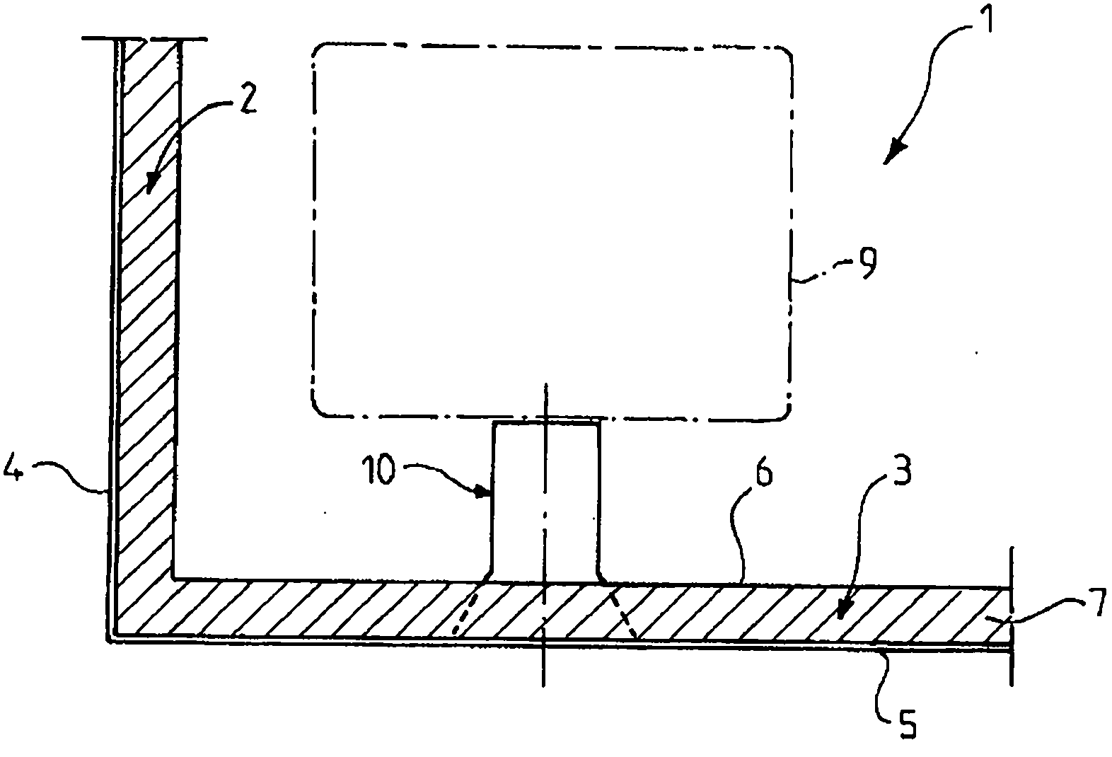
[0043] exist figure 1 Above, a sealed and thermally insulated container 1 can be partially seen, consisting of container walls 2 and 3 fastened to the inner surfaces of corresponding walls 4 and 5 of the load-bearing structure. The load-bearing structure is, for example, the inner hull of a double-hull ship or a building on the ground. To accommodate cold products such as GNL, the container wall comprises at least one sealing barrier 6 and at least one thermal insulating barrier 7 . For safety reasons, a secondary sealing barrier, not shown, can be provided between the load-bearing structure and the sealing barrier 6 , which in this case is called the primary sealing barrier.

[0044]The container 1 can be implemented according to known different geometries, for example prismatic geometries in ship hulls or above-ground cylindrical geometries or others. Furthermore, many methods are available for implementing the thermal and sealing barriers, for example using prefabricated ...


PUM


Abstract

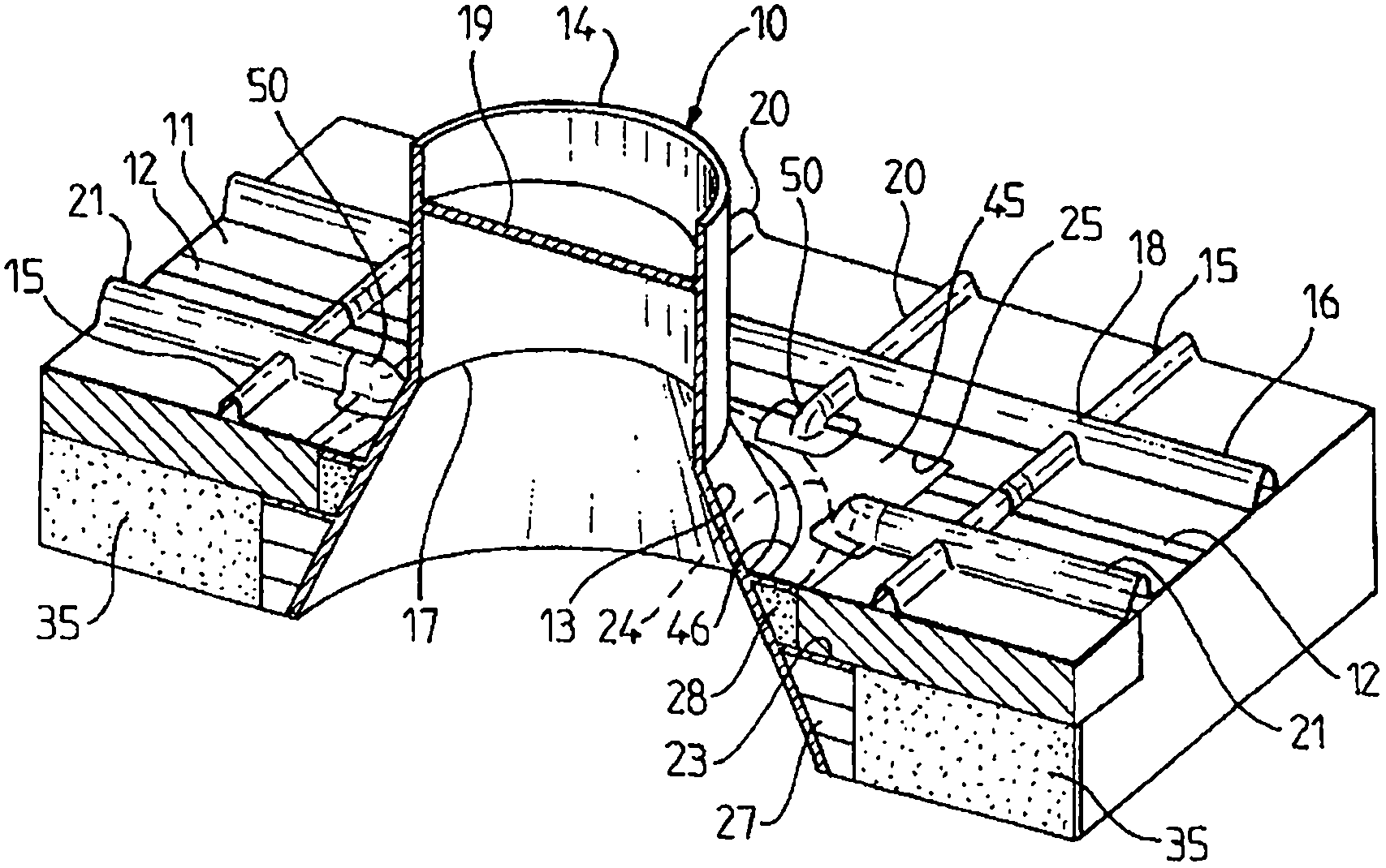
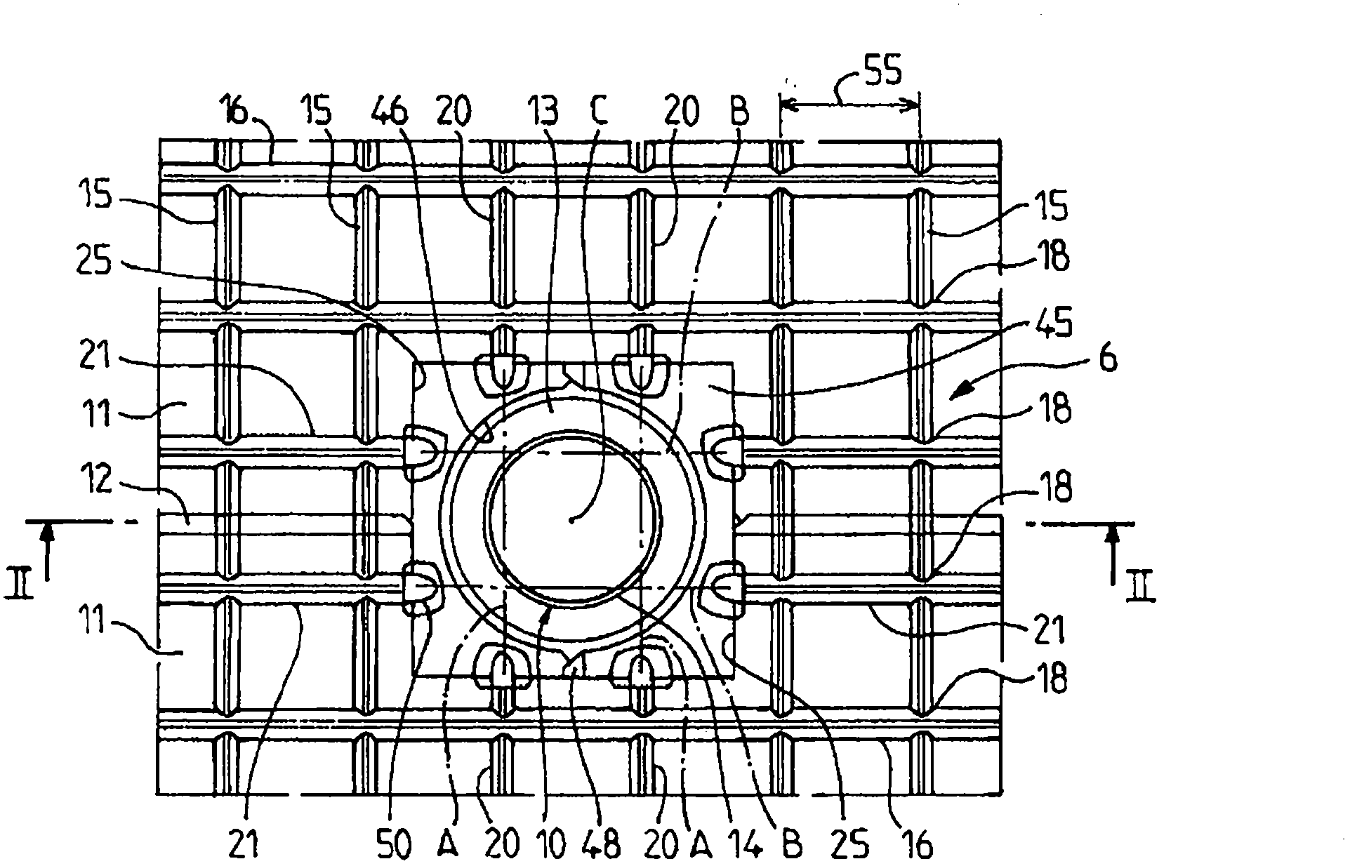
A vessel wall comprises a sealing barrier (6) and a support foot (10) for an item of equipment immersed in the sealed vessel. The sealing barrier comprises a corrugated metal sheet layer (11) having at least one series of parallel corrugations (15), the corrugated metal sheet layer being interrupted at a window (25) surrounding the support foot. The support foot extends longitudinally through the window. The sealing barrier comprises connecting parts (45, 50) for sealingly connecting the support foot to a marginal portion of the corrugated metal sheet layer that delimits the window. The window (25) interrupts the directrices of a plurality (20) of the parallel corrugations of the series, and the support foot is centred at a position situated between the directrices (A) of two parallel corrugations (20).

Description

technical field [0001] The invention relates to the field of the structure of sealed and thermally insulated containers arranged in load-bearing structures, and in particular the invention relates to the structure of the walls of such containers which are to receive feet. Background technique [0002] Sealed thermally insulated containers can be used in different industries to store hot or cold products. For example, in the energy field, liquefied natural gas (GNL) is a liquid that can be stored at approximately -163°C at atmospheric pressure in onshore storage containers or loaded in containers in floating structures. Such floating structures are in particular liquefied natural gas carriers and offshore facilities used for transporting products, notably known by the acronyms FPSO (Floating Production Storage Offloading Unit) and FSRU (Floating Storage and Regasification Unit). ) known for the storage, liquefaction or regasification of products. [0003] In membrane storag...

Claims


Application Information

Patent Timeline
IPC IPC(8): F17C3/02B63B25/16
CPCF17C2223/0161F17C2221/033F17C2270/0107F17C2260/01F17C2223/033F17C3/027F17C2205/018F17C2227/0135F17C2201/052F17C13/004B63B25/16F17C3/02
Inventor S·拉拉什J·布戈J·西戈德斯
Owner GAZTRANSPORT & TECHNIGAZ
Learn More