Triangle mesh water treatment flocculation reaction pool
A triangular grid and water treatment technology, applied in the direction of settlement tanks, etc., can solve the problems of high grid cost, increased grid cost, waste of materials, etc., shorten the construction period of water plants, save installation auxiliary materials, reduce The effect of labor intensity
- Summary
- Abstract
- Description
- Claims
- Application Information
AI Technical Summary
Problems solved by technology
Method used
Image
Examples
Embodiment approach 1
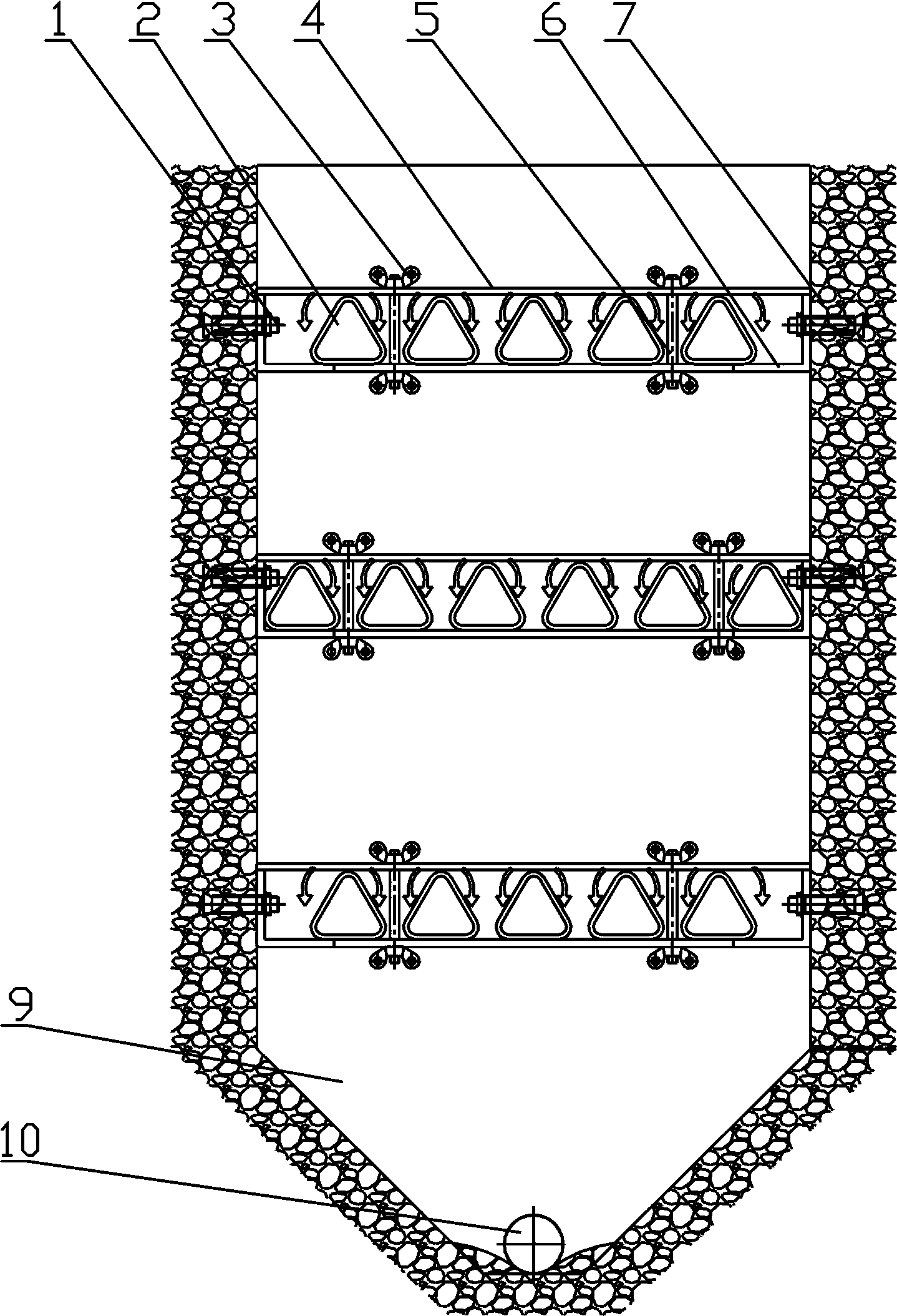
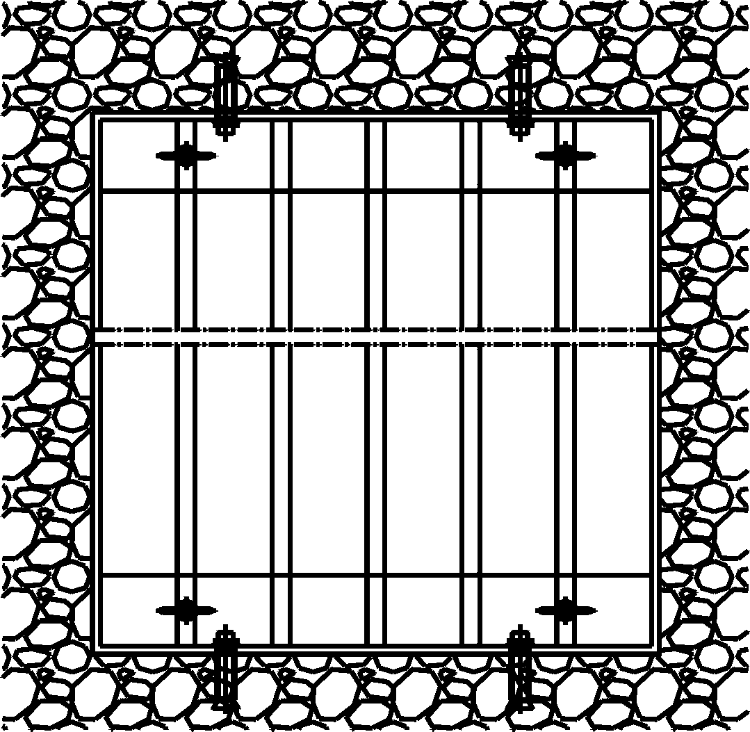
[0025] Implementation mode one: if figure 2 -3 shows:
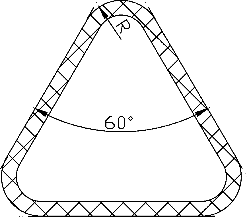
[0026] Adopt the triangular grid 2 whose cross-section is an equilateral triangle, the middle of the triangular grid 2 is hollow and adopts one-time injection molding, wherein the longitudinal ends of the triangular grid 2 are provided with flat steel 4, on the concrete shaft 7 according to The triangular grid 2 described in three layers is set in the upper, middle and lower layers, and multiple layers can also be set. Here, the interval between the upper layer and the middle layer is 600mm, the interval between the middle layer and the lower layer is 700mm, and the upper layer is 800mm away from its top surface. Wherein each layer of triangular mesh 2 is provided with flat steel 4 on the longitudinal ends, the longitudinal ends of triangular mesh 2 are connected and fastened by flat steel 4 and angle steel 6, and flat steel 4 penetrates through screw rod 5, and then passes through the upper and lower butterfly Shap...
Embodiment approach 2
[0027] Implementation mode two: if Figure 4 -5 shows:
[0028] A triangular mesh 2 with a regular triangle cross section is adopted, the middle of the triangular mesh 2 is hollow and formed by one-time injection molding, wherein the longitudinal ends of the triangular mesh 2 are provided with flat steel 4, and the supporting angle steel 6 passes through expansion bolts 1 are connected and fastened on the concrete shaft 7, and the triangular grid 2 whose section is an equilateral triangle is placed through the angle steel 6 at both ends as a whole. The triangular grid 2 is divided into multiple layers and arranged on the concrete shaft 7, wherein the grids of each layer are installed in dislocation. Here, on the concrete shaft 7, three layers of triangular grids 2 are set according to the upper, middle and lower layers. Here, the interval between the upper layer and the middle layer is 600 mm, the interval between the middle layer and the lower layer is 700 mm, and the upper ...
Embodiment approach 3
[0029] Implementation mode three: if Figure 6 -7 shows:
[0030] The triangular grid 2 whose cross section is an equilateral triangle is adopted, the middle of the triangular grid 2 is hollow and formed by one-time injection molding, wherein the longitudinal ends of the triangular grid 2 can save flat steel materials, and the supporting angle steel 6 is expanded by The bolts 1 are connected and fastened on the concrete shaft 7, and the triangular mesh 2 whose section is an equilateral triangle is placed through the angle steel 6 at both ends as a whole. The triangular grid 2 is divided into multiple layers and arranged on the concrete shaft 7, wherein the grids of each layer are installed in dislocation. On the concrete shaft 7, set the triangular grid 2 described in three layers according to the three-layer mode of the upper floor, the middle floor and the lower floor. Here, the interval between the upper floor and the middle floor is 600mm, the interval between the middle ...
PUM
| Property | Measurement | Unit |
|---|---|---|
| thickness | aaaaa | aaaaa |
Abstract
Description
Claims
Application Information
 - R&D
- Intellectual Property
- Life Sciences
- Materials
- Tech Scout
- Unparalleled Data Quality
- Higher Quality Content
- 60% Fewer Hallucinations
Browse by: Latest US Patents, China's latest patents, Technical Efficacy Thesaurus, Application Domain, Technology Topic, Popular Technical Reports.
© 2025 PatSnap. All rights reserved.Legal|Privacy policy|Modern Slavery Act Transparency Statement|Sitemap|About US| Contact US: help@patsnap.com


