Supercharge Your Innovation With Domain-Expert AI Agents!

Tyre vulcanizer laser lamp holder device

A technology of tire vulcanization and laser light, which is applied in the field of rubber machinery manufacturing, can solve the problems of high debugging cost and uncertain factors, single adjustable degree of freedom and orientation, and low debugging efficiency, so as to improve the success rate and debugging efficiency, make up for Uncertain factors have a large influence, and the effect of making up for the poor operability of visual inspection and manual shifting

Inactive Publication Date: 2013-02-20
BEIJING RES & DESIGN INST OF RUBBER IND
View PDF4 Cites 0 Cited by
  • Summary
  • Abstract
  • Description
  • Claims
  • Application Information

AI Technical Summary

Problems solved by technology

[0005] The object of the present invention is to provide a laser light stand device for a tire vulcanizer, which effectively compensates for the poor reliability, no fine-tuning structure, poor operability, low debugging efficiency, and ease of use in the existing light stand device and debugging method. The degree of freedom and orientation is single, the debugging cost and uncertain factors are large, and it has the advantages of multi-directional adjustment, simple operation, and excellent reliability.

Method used


Image

  • Tyre vulcanizer laser lamp holder device
  • Tyre vulcanizer laser lamp holder device
  • Tyre vulcanizer laser lamp holder device

Examples


Embodiment

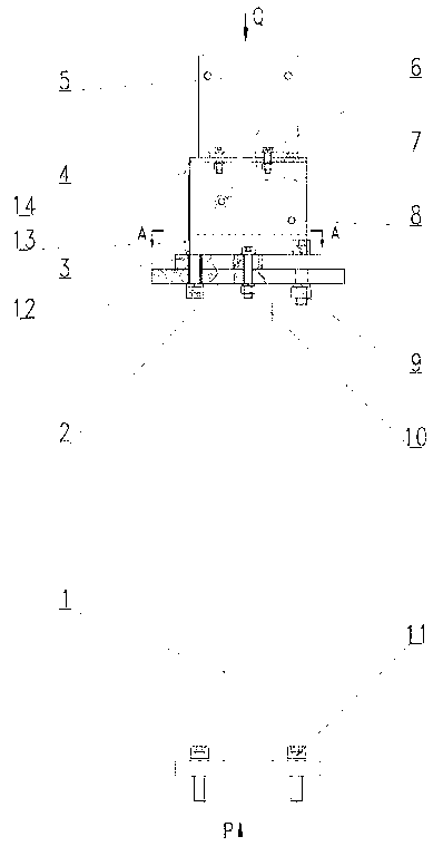
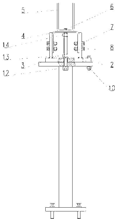
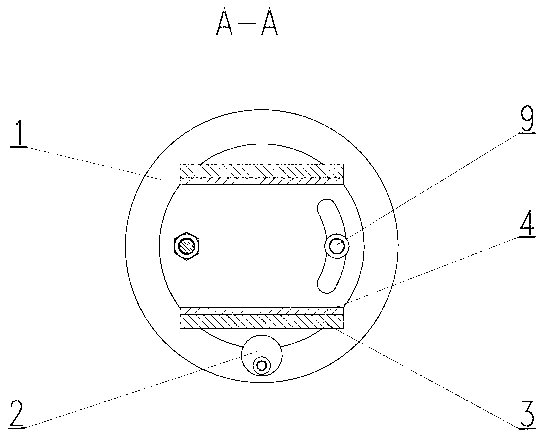
[0034] Example: in figure 1 , figure 2 Among them, the laser light stand device of the tire vulcanizing machine of the present invention consists of a base 1; an eccentric cam 2; an adjustment seat 3; an elevation angle adjustment seat 4; a mounting seat 5; Ⅲ8; fastening screw assembly Ⅳ9; locking nut Ⅰ10; fastening screw assembly Ⅴ11; long screw 12; locking nut Ⅱ13 and adjusting nut 14.

[0035] like image 3 As shown, the eccentric cam 2 adopts a cylindrical structure with a diameter of 30mm, and the distance between the eccentric axis and the center of the cylinder is 8mm; ° radian angle, see figure 1 . like Figure 5 As shown, the width of the long groove of the mounting plate under the base 1 is 13mm, and the length is 32mm; Figure 4 As shown, the long groove width on the mounting base 5 is 7mm, and the length is 80mm.

[0036] The working principle of the laser lamp lamp stand device of the tire vulcanizing machine of the present invention, seefigure 1 , in the ...


PUM


Abstract

The invention discloses a tyre vulcanizer laser lamp holder device, which mainly comprises: a base (1), an eccentric cam (2), an adjustment seat (3), an elevation angle adjustment seat (4) and a mounting seat (5). In a debugging process, right-and-left position rough adjustment can be conducted through a long groove on a mounting plate below the base (1). Right-and-left pivot angle fine adjustment can be carried out through the eccentric cam (2). Meanwhile, elevation angle fine adjustment can be performed by the elevation angle adjustment seat (4), so that a laser lamp can be made at an optimal position finally. The laser lamp holder device provided in the invention effectively makes up the defects of poor reliability, absence of fine adjustment structure, poor operability, low debugging efficiency, single adjustable freedom degree and direction, great debugging cost and uncertain factors, and the like in existing lamp holder devices, and effectively achieves the advantages of multidirectional adjustability, simple operation, and excellent reliability, etc.

Description

technical field [0001] The invention relates to a laser light lamp frame device for a tire vulcanizing machine, mainly relates to the design of a laser light light frame for a belt machine in a tire vulcanizing machine section in tire production machinery, and belongs to the technical field of rubber machinery manufacturing. [0002] Background technique [0003] After the tire vulcanization is completed, it needs to be transported to the next section through the tire pipe groove belt conveyor, and the belt conveyor needs to sense whether there are tires on the conveyor belt to be transported according to the laser light. Generally, the laser light emitting device is installed in the center of one end of the belt conveyor position, the laser light receiving device is installed on the other side of the belt conveyor to receive the signal. For a long time, due to the long travel of the belt conveyor, the general travel is about 30-80m, and the emission and reception range of ...

Claims


Application Information

Patent Timeline
Patent Type & Authority Applications(China)
IPC IPC(8): B29C35/00B29L30/00
Inventor 赵亮艾永安
Owner BEIJING RES & DESIGN INST OF RUBBER IND
Features
  • R&D
  • Intellectual Property
  • Life Sciences
  • Materials
  • Tech Scout
  • Unparalleled Data Quality
  • Higher Quality Content
  • 60% Fewer Hallucinations
Learn More