Automatic flame scarfing device

An automatic cleaning and flame technology, applied in gas flame welding equipment, welding equipment, metal processing equipment, etc., can solve the problems of high safety hazards, low production efficiency, and high production costs, achieve precise automatic positioning and fine-tuning, and improve production. Efficiency and the effect of reducing security risks

Inactive Publication Date: 2016-09-21
昆山慧伟拓机电科技有限公司
View PDF7 Cites 3 Cited by
  • Summary
  • Abstract
  • Description
  • Claims
  • Application Information

AI Technical Summary

Problems solved by technology

[0003] Nowadays, flame cleaning technology has been more and more widely used. In order to meet the melting requirements of the surface defects of steel billets on the production line, the production efficiency is not high and the safety hazard is high if manual cleaning is used, while the purchase of mechanical cleaning machines on the market will increase the production cost. High and difficult to meet the specific needs of manufacturers

Method used


Image

  • Automatic flame scarfing device

Examples


Embodiment Construction

[0014] The technical solutions of the present invention will be further described below in conjunction with the accompanying drawings and through specific implementation methods.

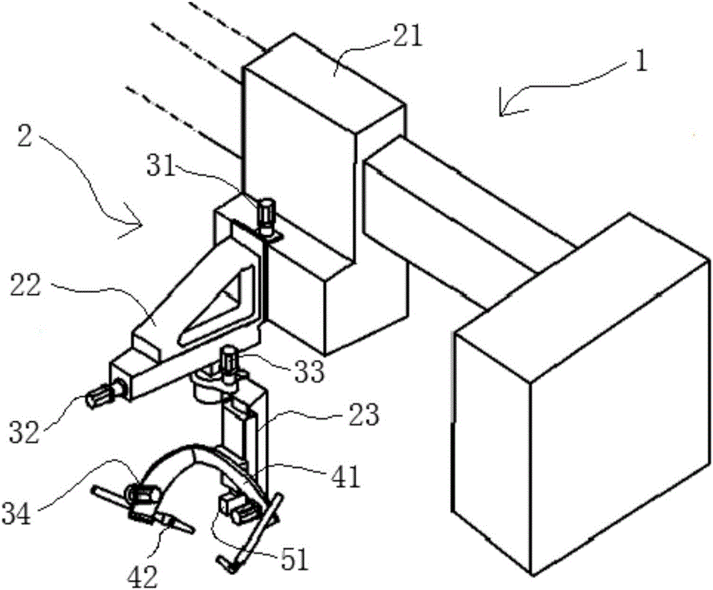
[0015] combine figure 1 As shown, a kind of automatic flame cleaning device in the present embodiment comprises gantry 1 and machine head 2, and machine head 2 comprises the base 21 that is slidably arranged on the crossbeam of gantry 1 and moves back and forth along the X-axis direction of gantry 1, and is slidably arranged. The cantilever beam 22 on one side of the base 21 and moves up and down along the Z-axis direction of the gantry 1, the rotating arm slidably arranged at the bottom of the cantilever beam 22 and reciprocating along the Z-axis direction of the gantry 1, the purging mechanism arranged at the bottom of the rotating arm, The servo drive mechanism for controlling the base 21, the cantilever beam 22, the rotating arm 23, and the fine adjustment of the purging mechanism, and the detec...


PUM


Abstract

The invention discloses an automatic flame scarfing device which comprises a gantry and a machine head, wherein the machine head comprises a base, a cantilever beam, a rotary arm, a blow-out mechanism, a servo driving mechanism and a detecting mechanism, wherein the base is slidably arranged on a cross beam of the gantry and performs to-and-fro motion in the X-axis direction of the gantry; the cantilever beam is slidably arranged on one side of the base and performs up-and-down motion in the Z-axis direction of the gantry; the rotary arm is slidably arranged at the bottom of the cantilever beam and performs to-and-fro motion in the Z-axis direction of the gantry; the blow-out mechanism is arranged at the bottom of the rotary arm; the servo driving mechanism is used for controlling fine adjustments of the base, the cantilever beam, the rotary arm and the blow-out mechanism; and the detecting mechanism is connected with the servo driving mechanism, and used for detecting a relative position between the blow-out mechanism and a workpiece. By adoption of such structural design, a flame spraying gun can be precisely and automatically positioned and fine adjusted under the drive of the servo driving mechanism and under the detection of the detecting mechanism, thereby effectively improving the production efficiency and reducing potential safety hazards.

Description

technical field [0001] The invention relates to the technical field of mechanical processing equipment, in particular to an automatic flame cleaning device. Background technique [0002] Flame cleaning is a process that uses high-temperature flame gas cutting and melting to burn off surface defects of steel billets. In billet production, it is an important process to ensure the quality of billets. Flame cleaning is a highly productive and inexpensive method of surface cleaning. The cost of cleaning billet with flame is more than half cheaper than cleaning with air shovel, and it is only one tenth of that of grinding wheel. And its cleaning speed is 10 to 15 times higher than that of the wind shovel, and it is widely used in cleaning carbon steel, low alloy steel and some alloy steel. [0003] Nowadays, flame cleaning technology has been more and more widely used. In order to meet the melting requirements of the surface defects of steel billets on the production line, the ...

Claims


Application Information

Patent Timeline
Patent Type & Authority Applications(China)
IPC IPC(8): B23K7/06B23K7/10
CPCB23K7/06B23K7/102
Inventor 胡俊
Owner 昆山慧伟拓机电科技有限公司
Why Eureka
Try Eureka