
Automatic plastering plate

A plastering board, automatic technology, applied in the direction of construction, building structure, etc., can solve the problems of labor efficiency and low, and achieve the effect of improving work efficiency

Inactive Publication Date: 2013-02-20
仇英兰
View PDF7 Cites 2 Cited by
  • Summary
  • Abstract
  • Description
  • Claims
  • Application Information

AI Technical Summary

Problems solved by technology

[0002] At present, when a bricklayer is building a building and plastering the walls, he usually places a gray basin with the mixed mortar in it. The bricklayer lifts the mortar with a pallet, and plasters the mortar on the wall with a plastering board, often with his left hand. board, right hand to smear, use both hands, very tiring and inefficient

Method used


Image

  • Automatic plastering plate

Examples


Embodiment Construction

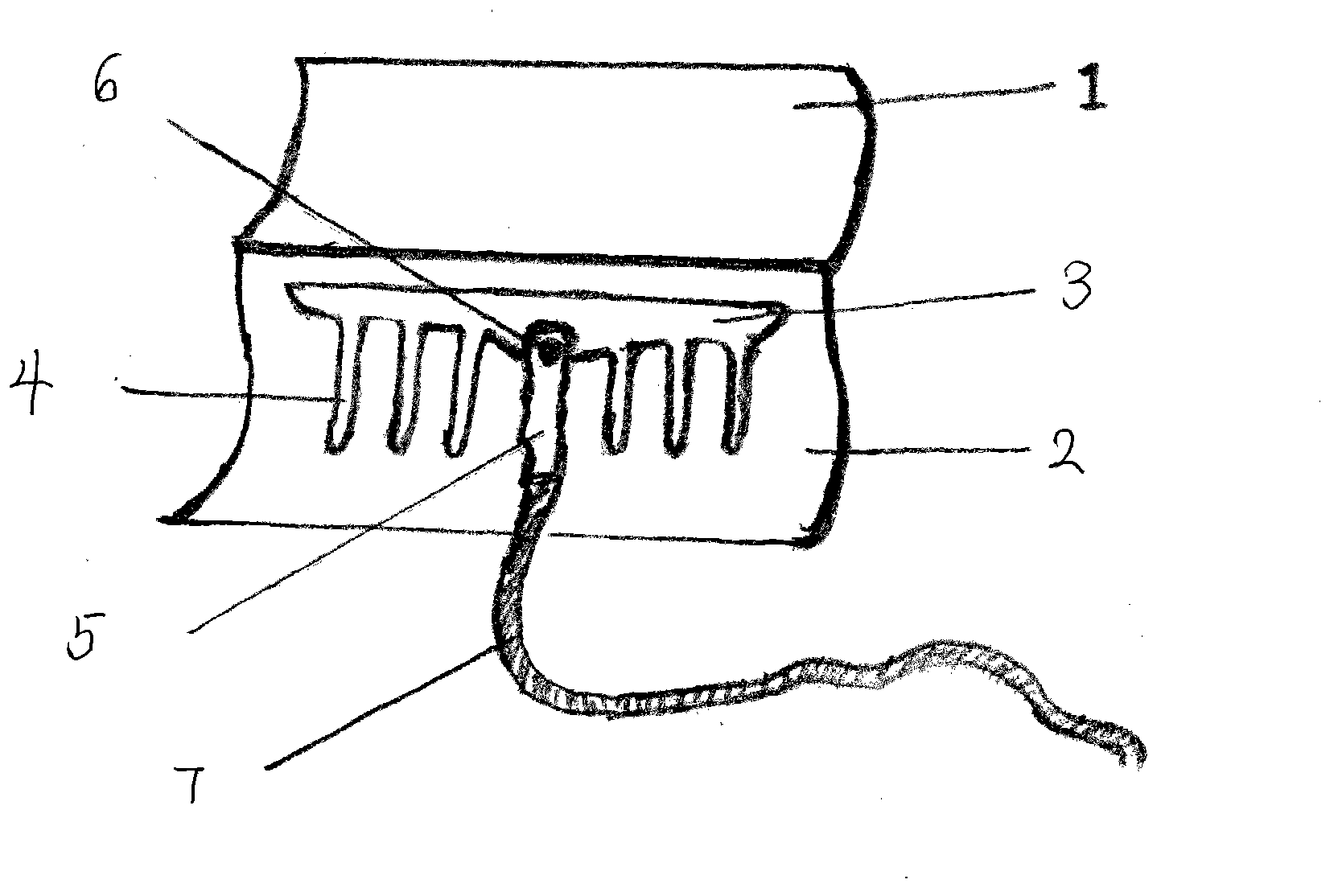
[0009] A square automatic plastering board made of stainless steel with a slightly folded middle and slightly warped upper and lower ends. It is divided into two parts: an upper plastering board and a lower plastering board. Connected, there is a switch on the handle. After it is turned on, the mortar is sent to the handle by the delivery pipe, and then to the convex groove and channel of the lower plastering board. Smoothing work, high efficiency and good effect.


PUM


Abstract

The invention discloses a stainless steel square automatic plastering plate of which the middle is slightly folded and the upper and lower ends are raised a little. The automatic plastering plate is composed of an upper plastering plate and a lower plastering plate, wherein a handle is arranged in an upward position of the lower plastering plate, and the inside of the handle is hollow and is connected with a conveying pipe; a switch is arranged on the handle; after the switch is turned on, the mortar is conveyed to the handle through the conveying pipe and enters a convex trough and a convex channel of the lower plastering plate; and a bricklayer holds the handle and drags up and down for uniform plastering. The automatic plastering plate can perform the primary plastering work of the wall, and realizes high efficiency and good effect.

Description

technical field [0001] The invention relates to an automatic plastering board, which belongs to the field of building appliances. Background technique [0002] At present, when a bricklayer is building a building and plastering the walls, he usually places a gray basin with the mixed mortar in it. The bricklayer lifts the mortar with a pallet, and plasters the mortar on the wall with a plastering board, often with his left hand. The board, the right hand to wipe the slurry, and both hands are used together, which is very tiring and inefficient. Contents of the invention [0003] In order to save the bricklayer's physical strength and improve work efficiency, the invention provides an automatic plastering board, which can be operated with one hand, and liberates the master bricklayer from heavy physical labor. [0004] The technical solution adopted in the present invention is: a square thin steel plate made of stainless steel, bent at the upper third, divided into upper w...

Claims


Application Information

Patent Timeline
Patent Type & Authority Applications(China)
IPC IPC(8): E04F21/06
Inventor 仇英兰
Owner 仇英兰
Learn More