Distributed power supply device

A distributed power supply and electron supply technology, applied in the direction of circuit devices, electrical components, power network operating system integration, etc., can solve the problems of difficulty in carrying and application, bulky flameproof layer, etc., and achieve convenient and efficient control, easy scalability, The effect of high security

Active Publication Date: 2013-02-20
SOUTHWEST UNIVERSITY
View PDF4 Cites 4 Cited by
  • Summary
  • Abstract
  • Description
  • Claims
  • Application Information

AI Technical Summary

Problems solved by technology

In order to solve the contradiction between safety and power, most of the existing high-power electrical equipment in explosive environments adopts explosion-proof treatment, but the explosion-proof layer itself that can be achieved at present is very heavy, which brings many difficulties to portability and application.

Method used


Image

  • Distributed power supply device
  • Distributed power supply device
  • Distributed power supply device

Examples


specific Embodiment approach

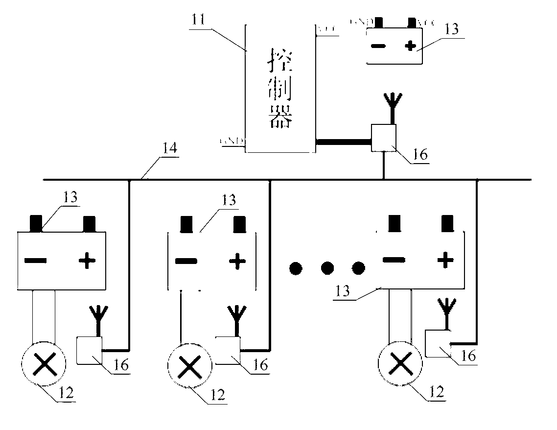
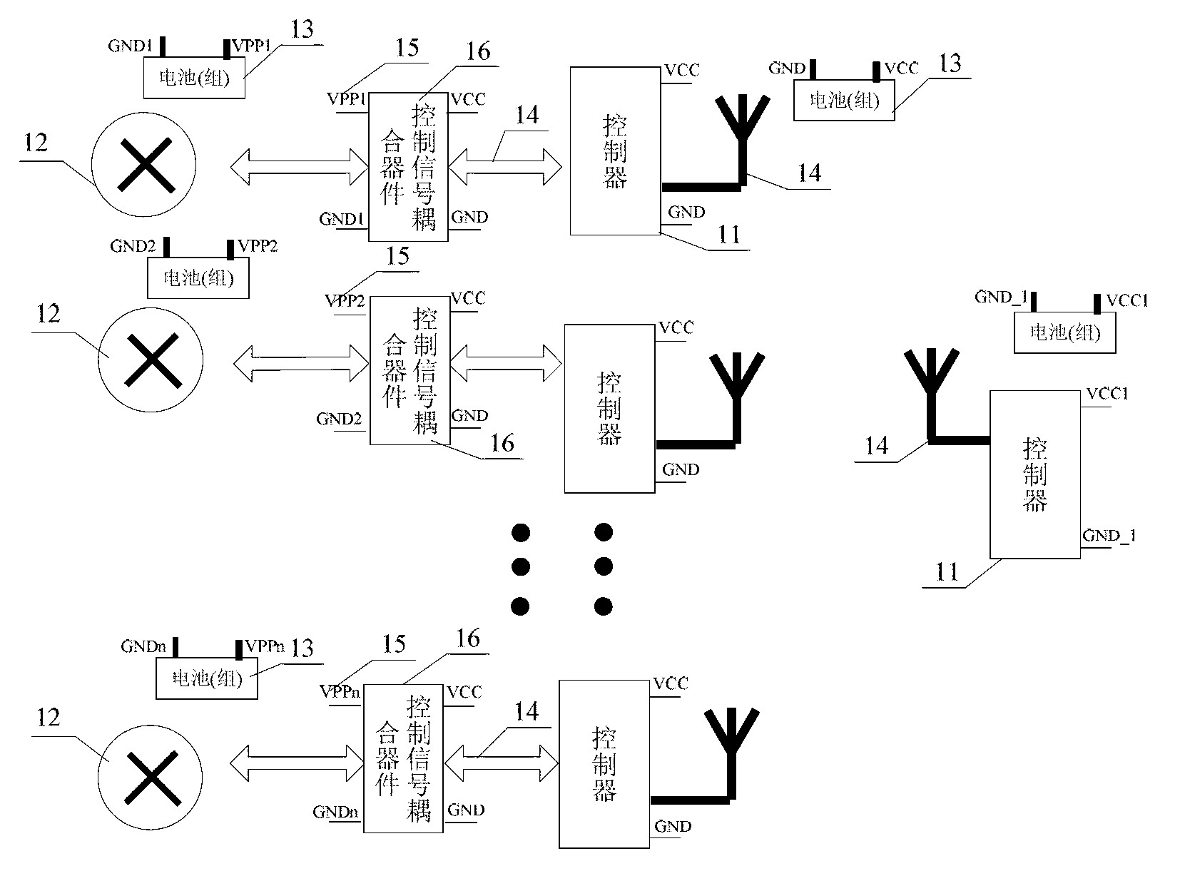
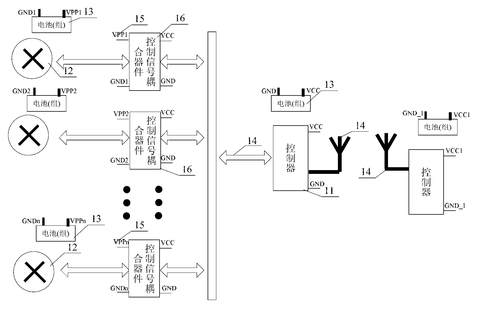
[0033] see figure 1 , a distributed power supply device disclosed in the present invention, including a control signal path 14, a control signal coupler 16, a plurality of batteries or battery packs 13, a plurality of electrical appliances 12, and connections between the batteries or battery packs and the corresponding electrical appliances A power supply line 15 and one or more controllers 11 connected to the signal path;

[0034] The combination of each battery or battery pack 13 and the corresponding electrical consumers 12 and power supply lines 15 constitutes a power supply subsystem, wherein the corresponding electrical consumers 12 in each power supply subsystem serve the same equipment;

[0035] Each power supply subsystem is electrically isolated from each other;

[0036] The input terminal of the control signal coupler 16 receives the control instruction transmitted by the control signal path 14, and outputs the control instruction to the electrical appliances 12, a...


PUM


Abstract

A distributed power supply device comprises a plurality of batteries or battery pack units which are cooperated to supply power for each electrical appliance of same equipment. The distributed power supply device comprises a controller, a control signal channel, a plurality of batteries or battery packs, a plurality of electrical appliances and a power circuit connecting the batteries or battery packs with the electrical appliances. Each battery or battery pack supplies power to one electrical appliance or a part of the electrical appliances. Physical isolation and electrical isolation are adopted among the plurality of the batteries or the battery packs, and among the corresponding electrical appliances, therefore, the plurality of batteries or battery packs and the corresponding electrical appliances can be taken as a plurality of independent units electrically, the electric power can be effectively distributed onto a plurality of independent lines, and further the safety of the system is improved in a specific environment. Meanwhile, the on/off state and the running state of each electrical appliance are uniformly controlled by the controller, so that the distributed power supply device has the advantages of central-station control and convenience in operation.

Description

technical field [0001] The invention belongs to the field of power supply systems, and in particular relates to a distributed combined power supply device. Background technique [0002] In disaster rescue, fire-fighting and detonation and other applications, the environment is often full of flammable and explosive gases, liquids or dust. In order to ensure safety, the voltage, current, inductance, capacitance and other characteristics of electrical appliances must meet certain requirements. For example, the national standard GB 3836 "Requirements for Explosive Atmospheres" Part 4 Figure A.1 gives the maximum allowable value of current / voltage for a purely resistive circuit. These limitations, especially the limitations of voltage and current, essentially limit the maximum power allowed by electrical appliances, thus greatly limiting the power consumption of some relatively high-power electrical appliances, such as high-power drive motors and high-power lighting equipment. ...

Claims


Application Information

Patent Timeline
Patent Type & Authority Applications(China)
IPC IPC(8): H02J13/00
CPCY04S40/126Y04S20/242Y02B70/3266Y02B90/2653Y02B70/30Y02B90/20
Inventor 王宇俊方灿李君科万婷葛耿育李飞龙谭艳万能清胡翔韩强孙亚芹
Owner SOUTHWEST UNIVERSITY
Why Eureka
Try Eureka