
Cylindrical permanent-magnet linear motor with modular C-shaped stator cores

A permanent magnet linear motor and stator core technology, applied in electrical components, electromechanical devices, electric components, etc., can solve the problems of increased motor length, unsuitable volume restrictions, etc., to reduce positioning force, meet small volume, enhance The effect of reliability

Active Publication Date: 2015-04-22
HUAWEI TEHCHNOLOGIES CO LTD
View PDF7 Cites 0 Cited by
  • Summary
  • Abstract
  • Description
  • Claims
  • Application Information

AI Technical Summary

Problems solved by technology

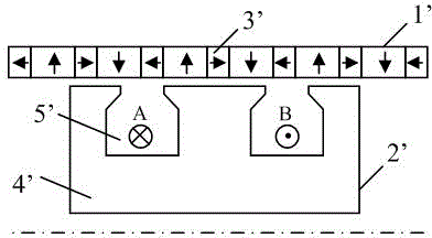
The offset function is achieved by adding a module with the opposite phase to it, which is to introduce another E-shaped iron core, so that the difference between the two E-shaped iron cores is 180° in electrical angle, and an additional structure with a phase opposite to the original structure is added, which will inevitably lead to The axial length of the motor is more than doubled, resulting in an increase in the length of the motor, which is not suitable for occasions with high volume limit requirements

Method used


Image

  • Cylindrical permanent-magnet linear motor with modular C-shaped stator cores
  • Cylindrical permanent-magnet linear motor with modular C-shaped stator cores
  • Cylindrical permanent-magnet linear motor with modular C-shaped stator cores

Examples


Embodiment Construction

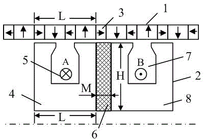
[0024] see figure 2 , the present invention includes an outer rotor ring 1 and an inner stator ring 2, the outer rotor ring 1 is composed of a Halbach array permanent magnet ring 3, and an axially magnetized permanent magnet is sandwiched between two permanent magnets with opposite radial magnetization directions , and the magnetization direction of two adjacent axially magnetized permanent magnets is also opposite. The axial width of the radially magnetized permanent magnet is twice the axial width of the axially magnetized permanent magnet.

[0025] The inner stator ring 2 is composed of a first C-shaped iron core 4 , a second C-shaped iron core 8 , an armature winding 5 and a magnetic barrier 6 . Both the first C-shaped iron core 4 and the second C-shaped iron core 8 are made of magnetically permeable materials, which can be formed by laminating punched sheets, and the magnetic barrier 6 is made of non-magnetically permeable materials.

[0026] The first C-shaped iron co...


PUM


Abstract

The invention discloses a cylindrical permanent-magnet linear motor with modular C-shaped stator cores, which is used in a small linear propulsion system. An inner stator ring is composed of armature windings, a magnetic barrier and two C-shaped cores, wherein the magnetic barrier is made of a non-magnetic material; the two C-shaped cores are made of a magnetic material and are the same in structure; the magnetic barrier is fixedly sandwiched between the two C-shaped cores; the two C-shaped cores are arranged in the axial direction; the distance between each C-shaped core and an outer rotor ring is the same; each C-shaped core is provided with a C-shaped groove; the opening of the C-shaped groove faces the outer rotor ring; one armature winding is embedded in each C-shaped groove; the axial length of the two C-shaped cores is one rotor polar pitch; and the axial width of the magnetic barrier is 1 / 4 of one rotor polar pitch. Thus, the two modular C-shaped core structures and a rotor generate positioning forces which are opposite in phase, thus realizing the counteraction of the positioning forces; the winds of the two phases achieve a physical circuit isolation effect and a temperature isolation effect, thereby being capable of realizing operation even in the case of a failure; and the magnetic barrier physically isolates the two modular C-shaped cores and decouples the magnetic circuit, thereby improving the operation fault tolerance of the motor.

Description

technical field [0001] The invention relates to a linear motor used in a small linear propulsion system, such as an artificial heart pump and the like. Background technique [0002] A linear motor is a motor that directly converts electrical energy into mechanical energy for linear motion. It does not require an intermediate transmission mechanism. It improves reliability and saves manufacturing costs. Therefore, it can replace rotary motors and is widely used in linear motion applications. At present, small linear motors have been used in the linear propulsion system of artificial hearts. The small space of artificial hearts has high requirements for the volume of the motors, and the motors are required to have high and relatively stable thrust density in a limited space. The thrust pulsation of the small motor can provide a larger and more stable thrust. In addition, in the application, the reliability requirements of the motor are relatively high, because the reliability...

Claims


Application Information

Patent Timeline
Patent Type & Authority Patents(China)
IPC IPC(8): H02K41/03
Inventor 吉敬华赵文祥严淑君房卓娅
Owner HUAWEI TEHCHNOLOGIES CO LTD
Learn More