A dual-edge plane three-phase linear permanent magnetic synchronization motor

A permanent magnet synchronous motor, flat plate technology, applied in electrical components, electromechanical devices, electric components, etc., can solve the problems of difficult design, complex winding insulation, high manufacturing cost, easy insulation process, reduced production cost, and high manufacturing cost. simple craftsmanship

Active Publication Date: 2010-12-08
HARBIN INST OF TECH
View PDF5 Cites 0 Cited by
  • Summary
  • Abstract
  • Description
  • Claims
  • Application Information

AI Technical Summary

Problems solved by technology

[0003] In order to solve the tooth pitch τ of the existing flat three-phase linear permanent magnet synchronous motor t and polar distance τ p The design is not easy to take into account, the ends of the windings of each phase cross each other, the ends of the windings are long, the copper loss is large, the winding insulation is complicated, and the manufacturing cost is high. The present invention designs a double-sided flat three-phase linear permanent magnet synchronous motor.

Method used


Image

  • A dual-edge plane three-phase linear permanent magnetic synchronization motor
  • A dual-edge plane three-phase linear permanent magnetic synchronization motor
  • A dual-edge plane three-phase linear permanent magnetic synchronization motor

Examples


specific Embodiment approach 1

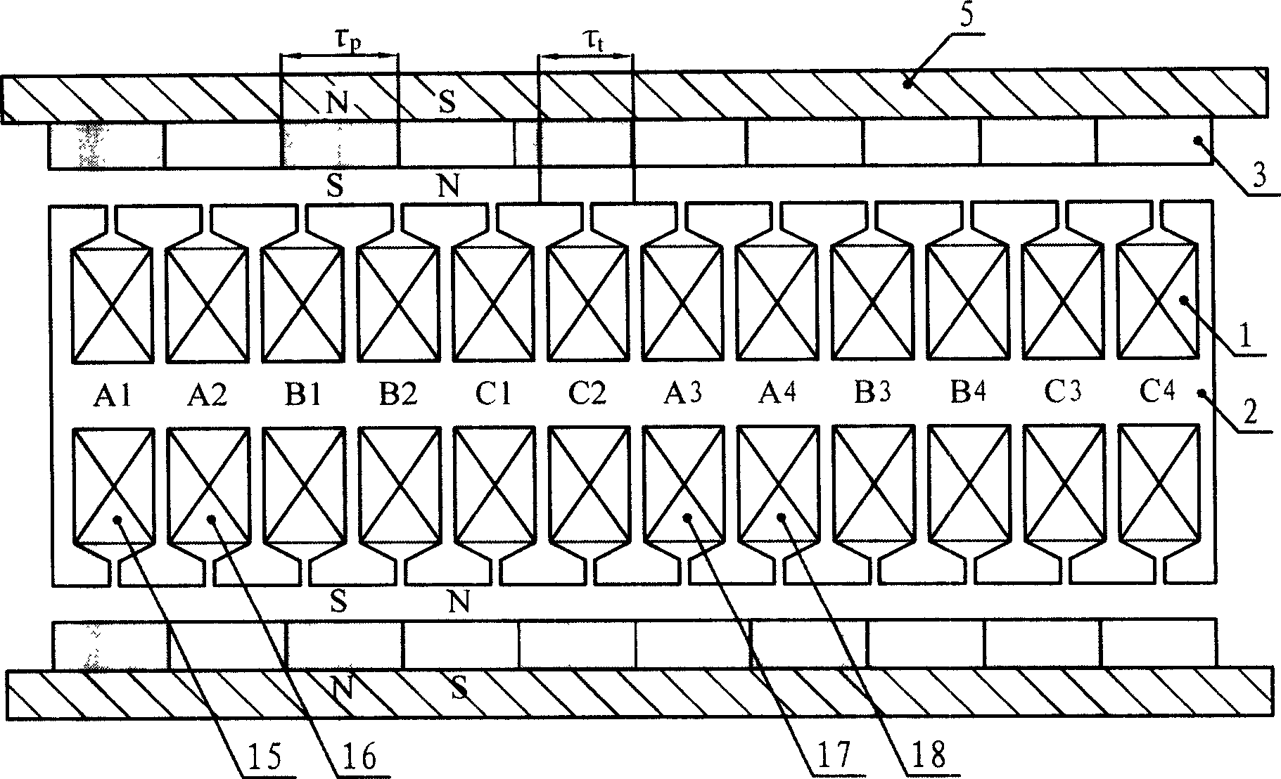
[0012] Specific implementation mode 1: see figure 1 This embodiment will be described. A bilateral flat three-phase linear permanent magnet synchronous motor in this embodiment is composed of a casing 5, an armature part and a permanent magnet excitation part, the casing 5 is made of a magnetically conductive material, and the permanent magnet excitation The component is composed of two groups of flat-shaped permanent magnets 3. The number of poles formed by the permanent magnets 3 is P=2k. The magnetization directions of the permanent magnets at the corresponding positions of the magnets 3 are opposite, that is, the polarities of the directions facing the armature components are the same, and the magnetization directions of the adjacent permanent magnets 3 in the same group of permanent magnets are opposite. The winding 1 and the armature iron core 2 are formed. The armature iron core 2 is fixed in the middle of the two flat plate-shaped permanent magnets 3 and has an air g...

specific Embodiment approach 2

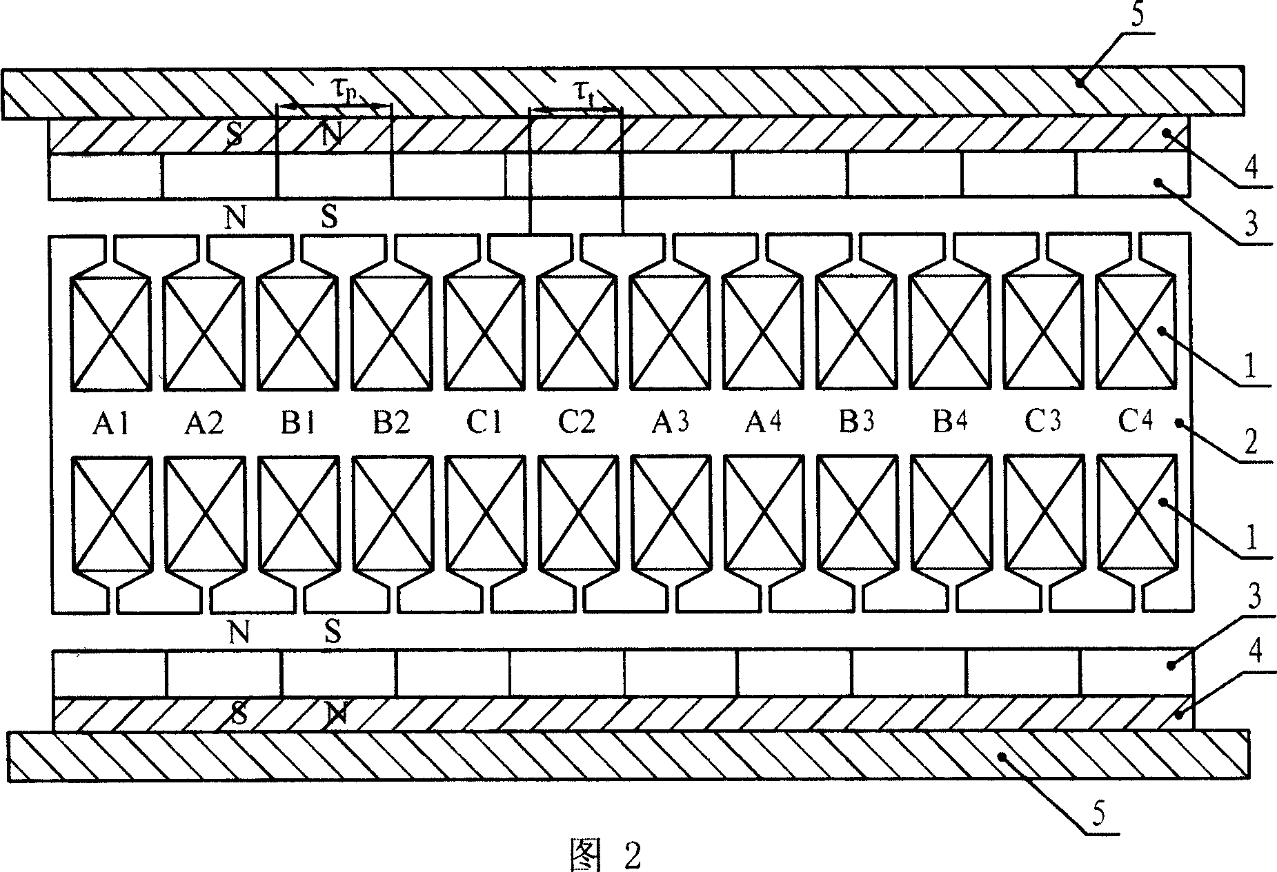
[0014] Specific implementation two: see figure 2 This embodiment will be described. The difference between this embodiment and the one-sided flat-phase three-phase linear permanent magnet synchronous motor described in Embodiment 1 is that the permanent magnet excitation component further includes a flat-plate permanent magnet yoke 4, and the permanent magnet yoke 4 is fixed between the permanent magnet 3 and the casing 5, and the casing 5 in this embodiment may be made of non-magnetic conductive material.

specific Embodiment approach 3

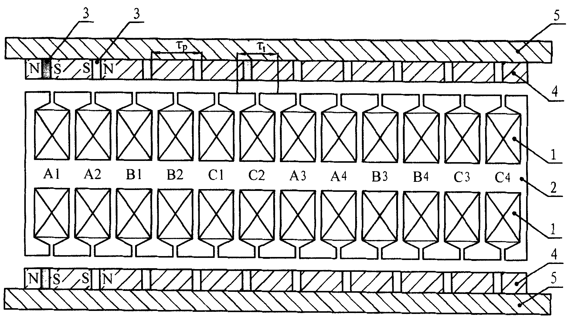
[0015] Specific implementation mode three: see image 3 , Figure 4 This embodiment will be described. The difference between this embodiment and the two-sided flat-phase three-phase linear permanent magnet synchronous motor described in the second embodiment is that the permanent magnets 3 are embedded in the permanent magnet yoke 4 and are arranged at intervals from the permanent magnet yoke, so The permanent magnets 3 are magnetized in parallel, the magnetization direction is parallel to the movement direction, the magnetization directions of the adjacent permanent magnets 3 are opposite, and the magnetization directions of the permanent magnets at the corresponding positions of the two groups of permanent magnets 3 on the bilateral casing 5 are respectively fixed. same.

[0016] When the casing 5 of the bilateral flat motor in this embodiment is made of magnetically conductive material, a layer of magnetic isolation plate 6 is added between the casing 5 and the permanent...


PUM


Abstract

A kind of two-sized flat three phase beeline permasyn motor, it relates to field of motor. Aiming at resolve problem that pitch Taut and polar distance Taup design is not easy to give attention to, every ends are across with each other, ends of coil is long, the copper cost is big, insulation of coil is complex, cost of manufacture is high of current flat three phase beeline permasyn motor, the invention designs a kind of two-sized flat three phase beeline permasyn motor. The invention includes armature part and permanent-magnet excitation parts; the armature part is nipped between the permanent-magnet excitation parts which are parallel with each other, two gases are between the armature part and two permanent-magnet excitation parts, thereinto the armature part mainly composes armature winding and armature iron core; the permanent-magnet excitation parts composes permanent-magnet. Iron core pitch Taut of the armature and polar distance Taup of the permanent-magnet fulfills the relation 3nTaut=(3n+-1)Taup, thereinto n is natural number. The beeline motor of the invention can be used as beeline motor, but also as the beeline generator, it possesses wide application foreground.

Description

technical field [0001] The invention relates to the field of motors, in particular to a flat-plate three-phase linear permanent magnet synchronous motor. Background technique [0002] The tooth pitch τ of the armature core of the traditional flat-plate three-phase linear permanent magnet synchronous motor t Pole distance τ from permanent magnet p The relationship 3τ is satisfied between t =τ p , This structure is called an integer tooth structure, that is, the number of teeth per pole and phase of the motor is an integer. The main problems of the linear permanent magnet synchronous motor with an integer tooth structure are: on the one hand, the positioning force of the motor caused by the tooth effect is large; On the other hand, the performance-to-volume ratio of the motor is low, which is mainly due to the p When the design is large, the magnetic yoke of the permanent magnet will be thickened, which will increase the volume and weight of the motor, and when the pole pi...

Claims


Application Information

Patent Timeline
Patent Type & Authority Patents(China)
IPC IPC(8): H02K41/03
Inventor 寇宝泉李立毅
Owner HARBIN INST OF TECH
Why Eureka
Try Eureka