Transverse magnetic flux magnetic field modulation type linear motor

A linear motor and magnetic field modulation technology, which is applied in the direction of electrical components, electromechanical devices, electric components, etc., can solve problems such as the reduction of fault tolerance performance, and achieve the effects of improved space utilization, simple adjustment, and improved harmonics

Active Publication Date: 2017-08-01
东莞希思克传动科技有限公司
View PDF3 Cites 0 Cited by
  • Summary
  • Abstract
  • Description
  • Claims
  • Application Information

AI Technical Summary

Problems solved by technology

The linear motor based on magnetic field modulation has been developed rapidly due to its advantages of compact structure, high power density and high efficiency, but there is coupling between the phases of the magnetic field, and the fault tolerance performance is reduced. Therefore, a transverse flux magnetic field modulation is proposed. On the one hand, the armature winding and the stator slots are perpendicular to each other in space, which realizes the decoupling of the electric load and the magnetic load, and can increase the output by increasing the rate of change of magnetic energy within a certain range; on the other hand, each phase They are decoupled from each other, which is convenient for independent control, and is easy to design into a multi-phase structure. In multi-phase operation, even if one phase is missing, it can work normally. The fault tolerance performance is good, and the reliability of the motor is improved.

Method used


Image

  • Transverse magnetic flux magnetic field modulation type linear motor
  • Transverse magnetic flux magnetic field modulation type linear motor
  • Transverse magnetic flux magnetic field modulation type linear motor

Examples


Embodiment Construction

[0022] The principles and features of the present invention are described below in conjunction with the accompanying drawings, and the examples given are only used to explain the present invention, and are not intended to limit the scope of the present invention.

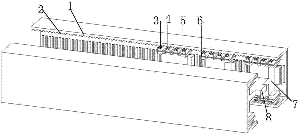
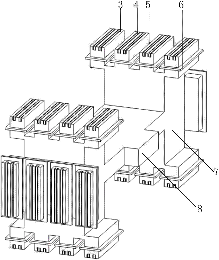
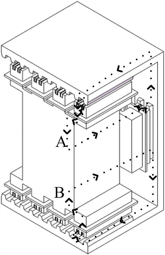
[0023] Please refer to figure 1 As shown, it is a structural schematic diagram of the transverse flux magnetic field modulation linear motor of the present invention, and the transverse flux magnetic field modulation linear motor includes: primary and secondary; the present invention combines magnetic field modulation on the basis of transverse flux A transverse flux magnetic field modulation type linear motor is proposed. The two secondary stages are made of silicon steel sheets, which are in the shape of a "C" and mirrored. There is no permanent magnet attached to the pivot winding, only simple secondary slots 1 and secondary teeth 2 are equidistantly distributed, and there are three-sided air gaps between the pri...


PUM


Abstract

The invention discloses a transverse magnetic flux magnetic field modulation type linear motor. The transverse magnetic flux magnetic field modulation type linear motor comprises primary stages and secondary stages; the two secondary stages are C-shaped and arranged in a mirror image manner; secondary stage grooves and secondary stage teeth are distributed on three surfaces on the inner side of the C shape in an equally spaced manner; three surfaces of air gaps exist between the primary stages and the secondary stages; each primary stage comprises two same primary stage iron cores and a connecting beam for connecting the two primary stage iron cores; same salient pole teeth in equally spaced distribution are arranged on the upper surfaces, the lower surfaces, and the surfaces, opposite to the connecting beam, of the primary stage iron cores; equidistant virtual teeth are arranged at the ends, close to the air gaps, of the salient pole teeth; the salient pole teeth are wound with armature windings; the adjacent armature windings are connected end to end; the winding direction of the armature windings on the upper surface of the salient pole teeth is opposite to that of the armature windings on the lower surface of the salient pole teeth; the winding direction of the armature windings on the surfaces, opposite to the connecting beam, of the salient pole teeth is the same as that of the armature windings on the lower surface of the salient pole teeth; the armature windings of the salient pole teeth on the three surfaces are connected in series to form one phase of windings; and permanent magnets are arranged at the ends, close to the air gaps, of the salient pole teeth.

Description

technical field [0001] The invention relates to a magnetic field modulation type linear motor, in particular to a transverse flux magnetic field modulation type linear motor. Background technique [0002] The linear direct drive motion system eliminates the need for complex mechanical conversion devices. The system has a simple structure, reliable operation, fast response and high control precision. It has a wide range of needs and applications in military and civilian industries such as aviation and aerospace. As the core component of the linear direct drive motion system, the linear motor has always been the preferred electric drive solution for the linear direct drive motion system, and it is also an effective means to solve the above problems. The linear motor based on magnetic field modulation has been developed rapidly due to its advantages of compact structure, high power density and high efficiency, but there is coupling between the phases of the magnetic field, and ...

Claims


Application Information

Patent Timeline
Patent Type & Authority Applications(China)
IPC IPC(8): H02K41/03
Inventor 赵玫王曼曼邹海林徐明铭杨洪勇王刚韩辅君邓冠龙张平张淑宁侯典立常新华刘慧霞
Owner 东莞希思克传动科技有限公司
Why Eureka
Try Eureka