
Electric tool

A technology of power tools and working heads, which is applied in the direction of power tools, manufacturing tools, portable power devices, etc., and can solve problems such as incompetence

Inactive Publication Date: 2013-02-27
苏州安必瑟斯机电技术有限公司
View PDF10 Cites 2 Cited by
  • Summary
  • Abstract
  • Description
  • Claims
  • Application Information

AI Technical Summary

Problems solved by technology

Such a tool is obviously incapable of screwing a screw in a gap of about 10 cm

Method used


Image

  • Electric tool
  • Electric tool
  • Electric tool

Examples


Embodiment Construction

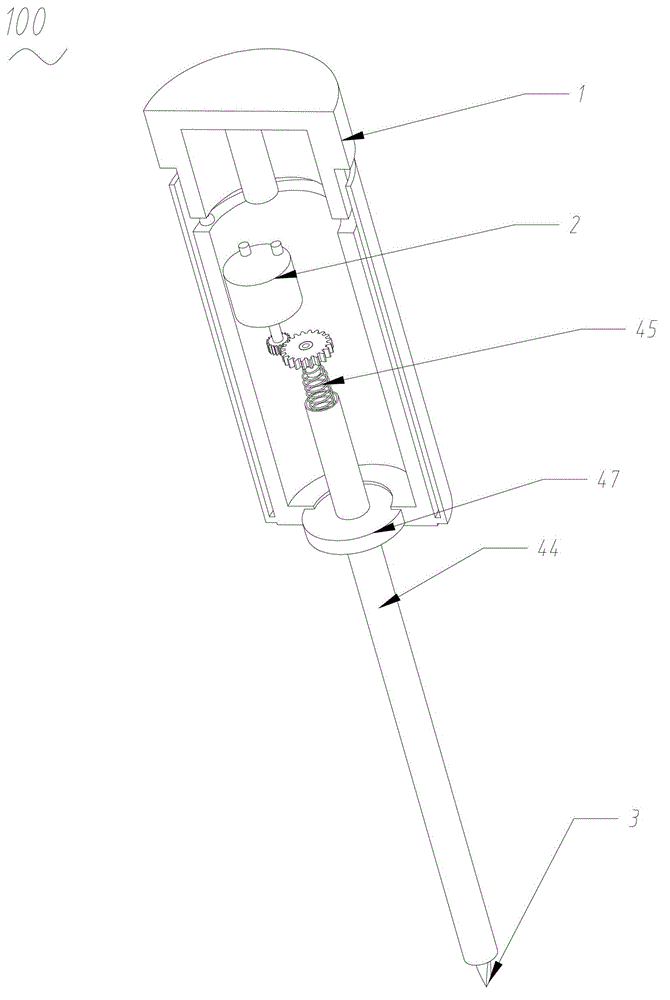
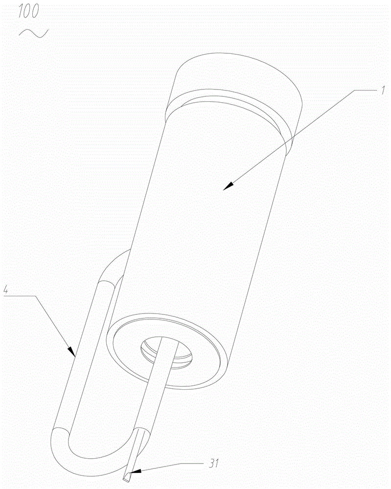
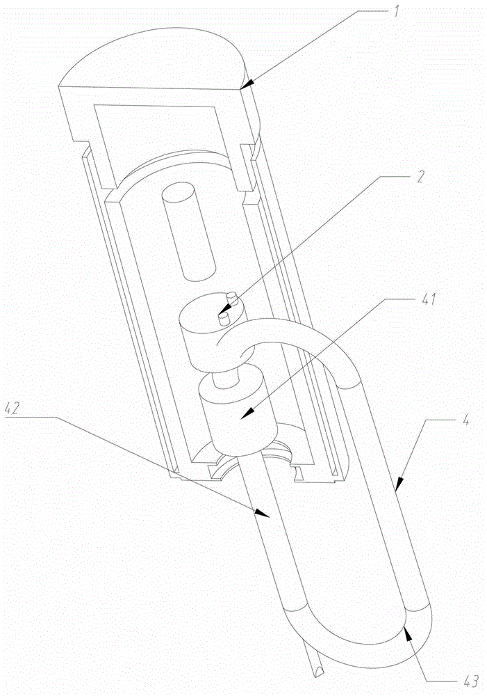
[0017] An electric tool 100, comprising a housing 1, a motor 2 accommodated in the housing 1, and an output shaft 31, the electric tool 100 is provided with a flexible conduction system 4, and the flexible conduction system 4 is driven by the motor 2 and connected to the output shaft 31 .

[0018] The housing 1 is used to accommodate the components of the electric tool 100 and to be held by an operator. The casing 1 is provided with a switch capable of controlling the motor 2 . The housing 1 is provided with a mounting slot for the motor 2 .

[0019] The motor 2 can be a DC motor 2 or an AC motor 2 . The motor 2 is electrically connected with the switch and controlled. The motor 2 is extended with a motor shaft. The motor shaft can be directly or indirectly connected to the flexible conduction system 4 .

[0020] The output shaft 31 is used to drive the working head. Due to the difference in the flexible conduction system 4, the structure of the output shaft 31 is also d...


PUM


Abstract

The invention provides an electric tool which comprises a shell, a motor arranged in the shell and an output shaft and is provided with a flexible conduction system, wherein the flexible conduction system is driven by the motor, is connected with the output shaft and can be used for transmitting the torque of the motor to the output shaft. Since the flexible conduction system is flexible, the electric tool can be operated under a narrow environment.

Description

technical field [0001] The invention relates to an electric tool. Background technique [0002] Traditional electric tools, such as screwdrivers, have a motor and a drive shaft connected to the motor. These drive shafts are completely rigid. The minimum size of the transmission shaft is also above 10 cm. Coupled with the size of the power tool itself, it is about 20 cm. Such a tool is obviously incapable of screwing a screw in a gap of about 10 centimeters. [0003] Therefore, on the basis of intensive research on the prior art, the inventor provides an electric tool used in a narrow space. Contents of the invention [0004] The purpose of the invention is to provide an electric tool that is easy to operate. [0005] In order to achieve the above object, the present invention provides an electric tool, which includes a housing, a motor accommodated in the housing, and an output shaft. connect. [0006] Compared with the prior art, the present invention has at least ...

Claims


Application Information

Patent Timeline
Patent Type & Authority Applications(China)
IPC IPC(8): B25B21/00B25F5/00
Inventor 陈艳红
Owner 苏州安必瑟斯机电技术有限公司
Learn More