Rotary air preheater sealing structure

A technology of air preheater and sealing structure, which is applied in the field of energy saving and environmental protection, and can solve the problems of short air leakage maintenance time of low air preheater, high price of superalloy materials, high processing accuracy and process requirements, and reduce direct air leakage, workmanship, etc. The effect of adapting to a wide range of conditions and avoiding maintenance work

Pending Publication Date: 2017-11-17
XIAN XIRE ENERGY SAVING TECH
View PDF3 Cites 1 Cited by
  • Summary
  • Abstract
  • Description
  • Claims
  • Application Information

AI Technical Summary

Problems solved by technology

[0018] The main disadvantages of this technology are: (a) Due to the mushroom-shaped deformation of the air preheater rotor in the hot state, the sealing slider and the fan-shaped plate will not be in a parallel contact state as in the cold installation
[0024] The main disadvantages of brush seals are: (a) high processing precision and process requirements, (b) high-temperature alloy materials are expensive, (c) bristles are easy to wear, low-air preheater air leakage maintenance time is short, and the transformation and replacement costs are relatively large, etc. shortcoming
With this technology, the air leakage rate can be controlled below 2% by increasing the power of the fan, but because a pressurized fan higher than the primary air pressure head is required, the overall power consumption is relatively large
In addition, due to the large amount of dust in the flue gas, the blades of the fan wear out quickly and have a short service life.
At present, this technology is only applied to the flue gas heat exchanger (GGH) system, and there is no report on the air preheater

Method used


Image

  • Rotary air preheater sealing structure
  • Rotary air preheater sealing structure
  • Rotary air preheater sealing structure

Examples


Embodiment Construction

[0060] The present invention is described in further detail below in conjunction with accompanying drawing:

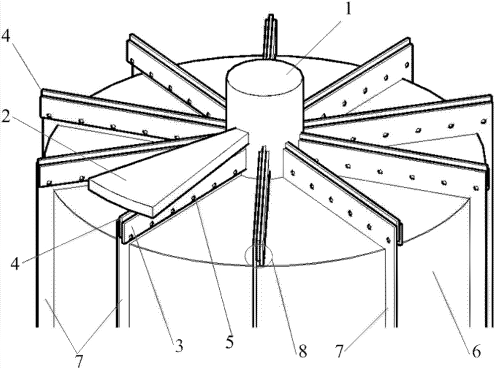
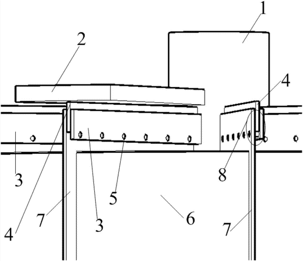
[0061] see figure 1 and figure 2 , The sealing structure of the rotary air preheater of the present invention is composed of a sealing groove 8 and a sealing plate 4, which are radially arranged on the rotor 6 of the air preheater, matching with the compartment structure of the air preheater. The sealing piece 4 is embedded in the sealing groove 8 , one end is fixed on the central tube 1 of the air preheater, and the other end is in a free state, completely independent of the sealing groove 8 . At the same time, there is a minimum reasonable gap between the top of the sealing sheet 4 and the fan-shaped plate 2 .

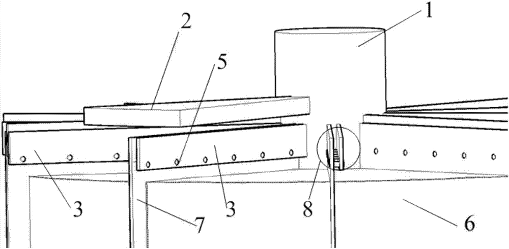
[0062] Such as image 3 As mentioned above, the seal groove 8 is formed by the seal groove side plate 3 and the rotor compartment partition 7, the seal groove side plate is connected by the bolt 5 at the bottom of the seal groove 8, forms a seal groove wi...


PUM


Abstract

The invention discloses a rotary air preheater sealing structure. The sealing structure is mainly composed of seal washers and seal grooves. The seal grooves are radially arranged on air preheater rotors. The corresponding seal washers are embedded into the seal grooves, and one end of each seal washer is fixed to a central cylinder of an air preheater; the other end of the seal washer is free. The bottoms of the seal washers are embedded into the seal grooves, and the minimum rational clearance is kept between the top of each seal washer and a sector plate. In operation, the seal grooves incline toward the peripheries of the rotors from the central cylinder, while only one section of the seal washers is fixed to the central cylinder, and does not incline with the central cylinder. In this way, the bottoms of the seal washers are still embedded into the seal groove for a certain depth to ensure the sealing effect; and the minimum clearance can still be kept between the top of the seal washer and the sector plate. The air leakage rate of the air preheater is ensured to be unchanged under different working conditions for a long time, and is kept at a low level. The rotary air preheater sealing structure disclosed by the invention has the advantages of rational and simple structure, little maintenance, uneasy jamming, abrasion or deformation, and wide application scope of working conditions, and is an important innovation of a rotary air preheater seal.

Description

technical field [0001] The invention belongs to the field of energy saving and environmental protection, and relates to a sealing structure of a rotary air preheater. Background technique [0002] At present, the main structures of air preheater seals are: a) air leakage control system (LCS); b) fixed seal; c) fixed double seal; d) fixed triple seal; e) shrapnel seal; f) hinge g) elastic self-adaptive seal; h) brush seal technology; i) hinge seal; j) gap self-compensation air leakage control system; k) dredging seal; l) pressurized seal technology. The main structural characteristics and application conditions of various types of sealing forms are as follows. [0003] a) Air leakage control system [0004] The air leakage control system of the air preheater is the technology such as Alstom that was first introduced by several major boiler factories, and it is also a common sealing method in China. The working principle of the seal is to use the sensor to automatically mon...

Claims


Application Information

Patent Timeline
Patent Type & Authority Applications(China)
IPC IPC(8): F23L15/00F28F11/00
CPCF23L15/00F28F11/00F28F2230/00Y02E20/34
Inventor 李杨王宏武井新经周元祥廖高良王勇林琳周刚
Owner XIAN XIRE ENERGY SAVING TECH
Why Eureka
Try Eureka