Thread clamping mechanism for hosiery circular knitting machine

A thread clamping mechanism and knitting machine technology, applied in knitting, weft knitting, textiles and papermaking, etc., can solve the problem that old loops are easy to float, wear and tear of Huff needles and knitting needles, and interfere with the work of Huff needles and knitting needles, etc. question

Active Publication Date: 2014-01-15
NINGBO CIXING
View PDF8 Cites 0 Cited by
  • Summary
  • Abstract
  • Description
  • Claims
  • Application Information

AI Technical Summary

Problems solved by technology

[0002] During the knitting process of the existing circular knitting machine, the machine is running at high speed. When the double-layered knitting of the half needle and the knitting needle is done, the old coil is very easy to float, which will interfere with the work of the half needle and the knitting needle, and it is easy to cause Bad phenomena such as missing stitches and wrong stitches will cause fabric defects and reduce the yield rate, and this phenomenon will cause wear to the huff needles and knitting needles, which will increase the probability of damage to the circular knitting machine and damage the user's economy. Benefit

Method used


Image

  • Thread clamping mechanism for hosiery circular knitting machine
  • Thread clamping mechanism for hosiery circular knitting machine
  • Thread clamping mechanism for hosiery circular knitting machine

Examples


Embodiment Construction

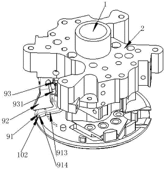
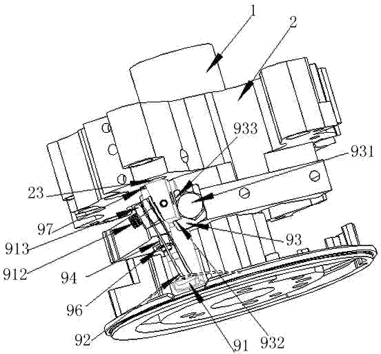
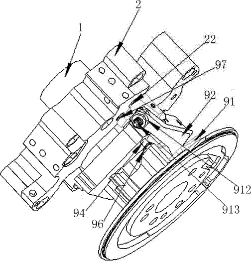
[0013] See attached picture. This embodiment includes a clamping base 91, the clamping base 91 is fixed on the air valve seat 2, and there is a clamping pneumatic piston 23 on the relative position of the valve seat 2, the clamping base 91 is L-shaped, in The upper end of the L-shaped vertical axial section has a protruding surface, on the protruding surface of the upper end of the clamping base 91, a pressure spring piece 92 is installed through a set screw 913 and a hex nut 912, and the pressure spring piece 92 is on the top. Narrow and wide trapezoid, there is a blocking piece 93 on one side of the protruding surface, the bottom end 932 of the blocking piece 93 can be in conflict with the bottom of the protruding surface of the clamping base 91, and the blocking piece 93 is installed on the gas cylinder by a hex head bolt 931. On the valve seat 2, the side of the blocking piece 93 is a guide surface 933, on the trajectory of the downward movement of the clamping base 91; on...


PUM


Abstract

The invention discloses a thread clamping mechanism for a hosiery circular knitting machine. The thread clamping mechanism is mounted on a huff disc seat, and comprises a tread clamping seat, wherein the thread clamping seat is fixed on an air valve seat; a thread clamping pneumatic piston is arranged at the opposite position of the air valve seat; the thread clamping seat is L-shaped; a projecting face is formed at the upper end of the vertical axial segment of the L shape; under program control, the thread clamping seat is pushed downward by the thread clamping pneumatic piston, so that the thread clamping seat moves downward; in the downward moving process, a block sheet guide surface is used for orientation, and the lower end is used for spacing; in the downward moving process of the thread clamping mechanism, the thread clamping seat can abut against the groove face of a second groove of the huff disc seat when contacting the groove face due to the bottom design of the thread clamping seat; and a projection distance is also left for the tread clamping seat, so that the thread clamping mechanism can rise to a certain degree after clamping the yarns passing through, thus preventing the phenomenon that after being clamped, the yarns to be knitted mistakenly enter a knitting zone to result in textile defectiveness and machine fault.

Description

technical field [0001] The invention belongs to the technical field of knitting machines, in particular to a thread clamping mechanism for hosiery circular knitting machines. Background technique [0002] During the knitting process of the existing circular knitting machine, the machine is running at high speed. When the double-layered knitting of the half needle and the knitting needle is done, the old coil is very easy to float, which will interfere with the work of the half needle and the knitting needle, and it is easy to cause Bad phenomena such as missing stitches and wrong stitches will cause fabric defects and reduce the yield rate, and this phenomenon will cause wear to the huff needles and knitting needles, which will increase the probability of damage to the circular knitting machine and damage the user's economy. Benefit. The main function of the clamping mechanism is to clamp the yarn to be woven, so its structure will directly affect the stability of its funct...

Claims


Application Information

Patent Timeline
Patent Type & Authority Patents(China)
IPC IPC(8): D04B15/38
Inventor 孙平范
Owner NINGBO CIXING
Why Eureka
Try Eureka