Laser focal spot light intensity distribution test device and test method

A light intensity distribution and testing device technology, applied in the field of optical detection, can solve problems such as poor practicability, CCD blinding, and affecting measurement results, and achieve the effects of compact structure, high degree of automation, and high system integration

Inactive Publication Date: 2015-07-29
XI'AN INST OF OPTICS & FINE MECHANICS - CHINESE ACAD OF SCI
View PDF7 Cites 0 Cited by
  • Summary
  • Abstract
  • Description
  • Claims
  • Application Information

AI Technical Summary

Problems solved by technology

Although the CCD can quantitatively test the light intensity distribution of the laser focal spot, for strong lasers, the direct measurement of the CCD may "blind" the CCD, and the test risk is greater
At the same time, generally, the engraved window at the front end of the CCD is parallel glass, which is prone to interference and affects the measurement results; the risk of using photosensitive paper to test is small, but the measured light intensity distribution map of the focal spot needs to be transformed by professional equipment to obtain quantified light intensity. Distribution, intermediate conversion errors are large, time-consuming and labor-intensive, and poor in practicability

Method used


Image

  • Laser focal spot light intensity distribution test device and test method

Examples


Embodiment Construction

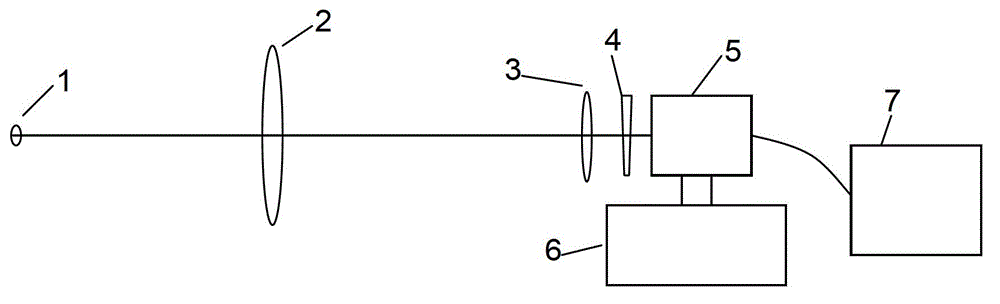
[0023] see figure 1 , the present invention provides a laser focal spot light intensity distribution testing device, the laser focal spot light intensity distribution testing device comprises a relay mirror 3, an attenuation board 4, an adjustment frame 6 and a CCD arranged on the adjustment frame 6; The focal spot 1 of the measuring laser, the relay mirror 3, the attenuation plate 4 and the CCD are on the same optical axis in sequence.

[0024] The laser focal spot light intensity distribution test device also includes an objective lens 2 arranged between the laser focal spot 1 to be tested and the relay mirror 3 .

[0025] The laser focal spot light intensity distribution testing device also includes a control computer 7 connected with the CCD.

[0026] The CCD is a CCD5 without a window; the attenuation chip 4 is an attenuation chip 4 that can eliminate laser interference.

[0027] When the present invention provides the above-mentioned test device, it also provides a met...


PUM


Abstract

The invention relates to a test device and a test method for laser focal spot light intensity distribution. The test device for laser focal spot light intensity distribution comprises a relay lens, an attenuation wedge plate, an adjusting bracket and a CCD (charge-coupled device), wherein the CCD is arranged on the adjusting bracket, and a laser focal spot to be measured, the relay mirror, the attenuation wedge plate and the CCD are sequentially positioned on one optical axis. The test device and the test method for laser focal spot light intensity distribution, provided by the invention, have the advantages that the integration degree is high, the structure is compact and the automation degree is high.

Description

technical field [0001] The invention belongs to the field of optical detection, and relates to a laser focal spot light intensity distribution testing device and a testing method, in particular to a strong laser focal spot light intensity distribution testing device and a testing method. Background technique [0002] In the Shenguang III host device, before reaching the target point in the main optical path, the laser beam must go through step-by-step amplification, transmission, shaping and sampling, and finally reach the target point. Somewhere in the transmission optical path, to monitor the quality of the laser beam here, it is usually possible to analyze the characteristics of the transmitted laser by measuring the intensity distribution of the laser focal spot in the sampling laser optical path. Therefore, the measurement of the intensity distribution of the laser focal spot very important. [0003] Traditional test method: Place the CCD or photosensitive paper at the...

Claims


Application Information

Patent Timeline
Patent Type & Authority Patents(China)
IPC IPC(8): G01J1/00
Inventor 陈永权段亚轩赵建科李坤胡丹丹
Owner XI'AN INST OF OPTICS & FINE MECHANICS - CHINESE ACAD OF SCI
Why Eureka
Try Eureka