
Ambient interference resisting method for testing electromagnetic radiation emission field

A technology of electromagnetic radiation emission and environmental interference, which is applied in the field of radiation emission characteristic testing, can solve problems such as harsh conditions of use, failure, and unsatisfactory use conditions, and achieve the effect of suppressing environmental interference and accurate radiation emission characteristics

Inactive Publication Date: 2013-02-27
NAT UNIV OF DEFENSE TECH
View PDF4 Cites 26 Cited by
  • Summary
  • Abstract
  • Description
  • Claims
  • Application Information

AI Technical Summary

Problems solved by technology

However, due to harsh conditions of use and many restrictions, its use is not ideal, especially when the interference signal in the environment has the same frequency component as the radiation signal of the device under test, the method basically fails

Method used


Image

  • Ambient interference resisting method for testing electromagnetic radiation emission field
  • Ambient interference resisting method for testing electromagnetic radiation emission field
  • Ambient interference resisting method for testing electromagnetic radiation emission field

Examples


Embodiment Construction

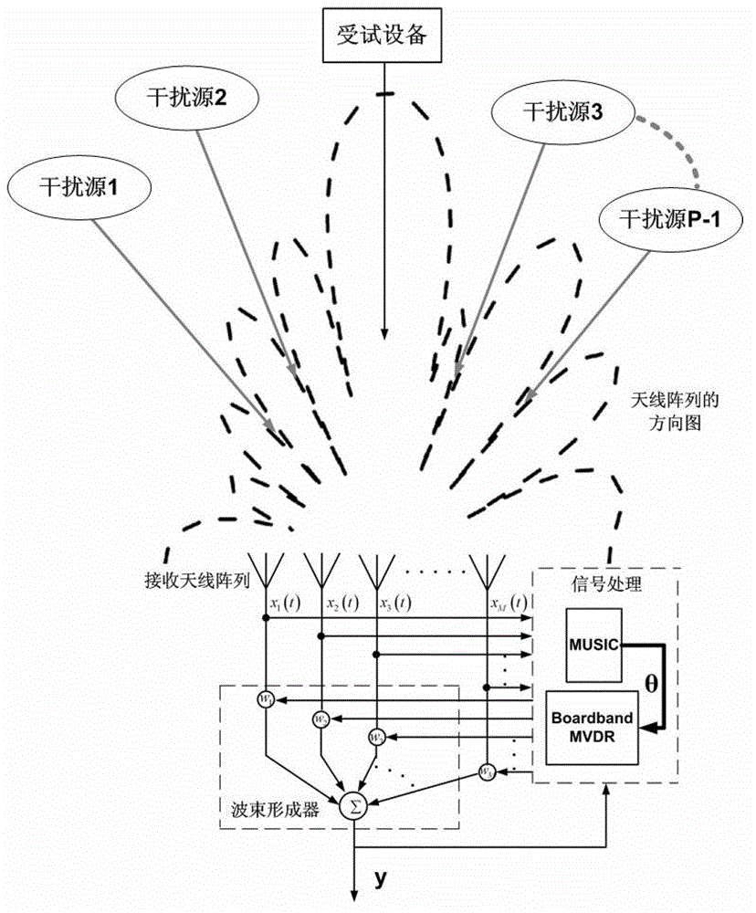
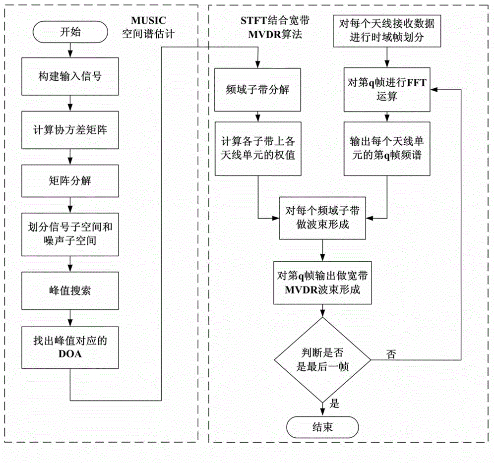
[0011] Attached below figure 1 The present invention will be described in detail.

[0012] Assume that there are P signals in the space at the same time, including the transmission signal of the device under test, and the receiving array is an M-element uniform linear array, and the array element spacing is d.

[0013] The first step is to construct the input signal matrix;

[0014] All radiation signals in space are recorded as s(t)=[s 1 (t),s 2 (t),...,s P (t)], the angle between the incident direction and the array normal direction is denoted as θ=[θ 1 ,θ 2 ,…,θ P ], defining the array-steering vector of the i-th signal:

[0015] α(ω i )=[1,exp(-jω i ),…,exp(-j(M-1)ω i )] T (1)

[0016] where ω i =2πdsinθ i / λ i . The signal received on the kth array element can be obtained as:

[0017] x k ( t ) = Σ i ...


PUM


Abstract

The invention discloses an ambient interference resisting method for testing an electromagnetic radiation emission field. The method specifically includes that a receiving antenna array is arranged in the testing field, each antenna unit can receive mixed signals composed of a tested device radiation signal and an interference signal, and by means of a spatial spectrum estimation method based on a multiple signal classification algorithm (MUSIC), the direction of arrival of each signal is obtained. According to a spatial spectrum estimation result, by means of a minimum variance distortionless response (MVDR) beam forming criterion, each antenna array element receiving signal is subjected to optimal weighting, in the premise that the tested device radiation signal is not distorted, array beams form null steering along the coming direction of the interference signal, and spatial filtering of the interference signal is achieved. According to the ambient interference resisting method, the MUSIC spatial spectrum estimation method and the MVDR beam forming technology are introduced into the field of electromagnetic compatibility testing, so that the ambient interference generated during testing of field radiation emission can be effectively inhibited, and radiation emission characteristics of a tested device in actual work environment can be accurately obtained.

Description

technical field [0001] The invention relates to the radiation emission characteristic test in the field of electromagnetic compatibility testing, and the main purpose is to obtain the radiation emission characteristic of emission equipment on a large-scale equipment platform relatively accurately in a complex electromagnetic environment on site. Background technique [0002] When implementing platform or system-level electromagnetic interference investigation and diagnosis, it is necessary to conduct on-site radiation emission characteristics tests on the transmitting equipment, but at this time, the test accuracy is easily affected by the interference of other transmitting equipment in the environment and cannot truly reflect the emission under test. The radiated emission characteristics of the equipment (device under test), how to effectively suppress the interference signal in the environment to obtain the real emission characteristics of the equipment under test has been ...

Claims


Application Information

Patent Timeline
IPC IPC(8): G01R29/08
Inventor 卢中昊刘继斌刘培国黄记军周东明李高升覃宇建薛国义
Owner NAT UNIV OF DEFENSE TECH
Learn More