
Touch display driving method for embedded touch screen

An embedded touch screen and touch-driven technology, which is applied in the fields of optics, instruments, and electrical digital data processing, etc., can solve the problems of touch screens not working normally, complex implementation, and poor touch effect

Inactive Publication Date: 2013-02-27
BEIJING BOE OPTOELECTRONCIS TECH CO LTD
View PDF4 Cites 10 Cited by
  • Summary
  • Abstract
  • Description
  • Claims
  • Application Information

AI Technical Summary

Problems solved by technology

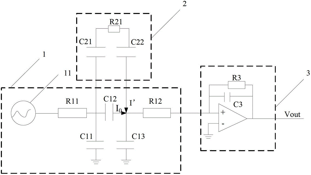
[0007] Since both the touch driving electrodes and the touch sensing electrodes are arranged in the liquid crystal display panel, the distance between the TP structure and the LCD common electrodes is very small, and the parasitic capacitance 104 between the touch driving electrodes / touch sensing electrodes and the common electrodes is very large, making the LCD Noise has a great impact on TP; therefore, the current signal detected by the touch point detection circuit is almost lost in the noise, and the touch effect is very poor, which may even cause the touch screen to fail to work normally.
[0008] In addition, the existing touch display driving method drives the embedded touch screen. In order to achieve a better touch effect, the touch screen needs to be connected to a reference ground point, and the specific implementation is relatively complicated.

Method used


Image

  • Touch display driving method for embedded touch screen
  • Touch display driving method for embedded touch screen
  • Touch display driving method for embedded touch screen

Examples


Embodiment 1

[0069] Take gate lines as touch driving electrodes as an example.

[0070] see Figure 5 , The touch screen provided by the embodiment of the present invention includes: a plurality of grid lines 1 arranged horizontally, the grid lines are arranged on the first substrate 2, and also includes: a plurality of touch sensing electrodes 3 arranged vertically, and the driving IC is the touch sensing electrode 3 Apply a constant voltage V 0 , and apply a touch drive voltage V for gate line 1 1 An electric field is formed between the touch sensing electrodes 3 and the grid lines 1 , and slits are provided between adjacent touch sensing electrodes 3 to achieve better touch effect and touch accuracy.

[0071] The touch sensing electrodes 3 can be arranged on the first substrate 2 or on the second substrate ( Figure 5 not reflected in).

[0072] The following describes how to apply a voltage V of a certain frequency to the touch drive electrode (gate line) without affecting the norm...

Embodiment 2

[0083] Figure 5 The shown touch driving electrodes may be touch driving electrodes independent of the grid lines, for example: conductive electrodes additionally arranged on the first substrate 2 may be used as touch driving electrodes, and the conductive electrodes may be arranged on a different layer from the grid lines, and The non-display area arranged laterally between the pixel units avoids affecting the aperture ratio of the pixels.

[0084] When the touch drive electrodes are independent touch drive electrodes arranged horizontally, a voltage V of a certain frequency is applied to each touch drive electrode of the touch screen. 1 ,Specifically:

[0085] A touch driving voltage is applied to the touch driving electrodes through a touch driving circuit independent of the display driving circuit.

[0086] To sum up, the embodiment of the present invention provides an in-cell touch screen touch display driving method, which applies a constant voltage V to each touch sen...


PUM


Abstract

The invention discloses a touch display driving method for an embedded touch screen, which is used for improving the touch effect of the embedded touch screen. The touch display driving method for the embedded touch screen comprises the following steps: in the touch and control period, applying constant voltage V0 to each touch sensing electrode of the touch screen; and applying touch driving voltage V1 with the frequency of 5 to 20 MHz to each touch driving electrode of the touch screen so as to form an electric field between the touch sensing electrode with the applied voltage V0 and the touch driving electrode with the applied voltage V1 and realize the touch function.

Description

technical field [0001] The invention relates to the technical field of touch display, in particular to an embedded touch screen touch display driving method. Background technique [0002] As an input medium, a touch panel (TP) is integrated with a display screen as a touch screen, and the touch screen plays an important role in the display field. [0003] Among them, the capacitive touch screen has attracted much attention because of its high sensitivity. The mutual capacitive touch screen is favored by people because of its high sensitivity and advantages of multi-touch. Capacitive touch screens include: external touch screens and built-in touch screens. Embedded touch screen refers to a touch screen that integrates TP into a liquid crystal display panel (Liquid Crystal Display, LCD). Embedded touch screen has become a research hotspot because of its low production cost, good light transmittance, thin module thickness and other reasons. [0004] The following briefly in...

Claims


Application Information

Patent Timeline
Patent Type & Authority Applications(China)
IPC IPC(8): G06F3/041G02F1/1333
Inventor 丁小梁吴俊纬王海生任涛杨盛际
Owner BEIJING BOE OPTOELECTRONCIS TECH CO LTD
Learn More