undercut tool

A technology for tools and cutting surfaces, which is applied in the direction of manufacturing tools, metal processing, drilling accessories, etc., and can solve problems such as drill damage

Inactive Publication Date: 2015-09-02
OBELIX HLDG
View PDF16 Cites 0 Cited by
  • Summary
  • Abstract
  • Description
  • Claims
  • Application Information

AI Technical Summary

Problems solved by technology

Unintentional activation of the drill under these conditions could result in serious injury

Method used


Image

  • undercut tool
  • undercut tool
  • undercut tool

Examples


Embodiment Construction

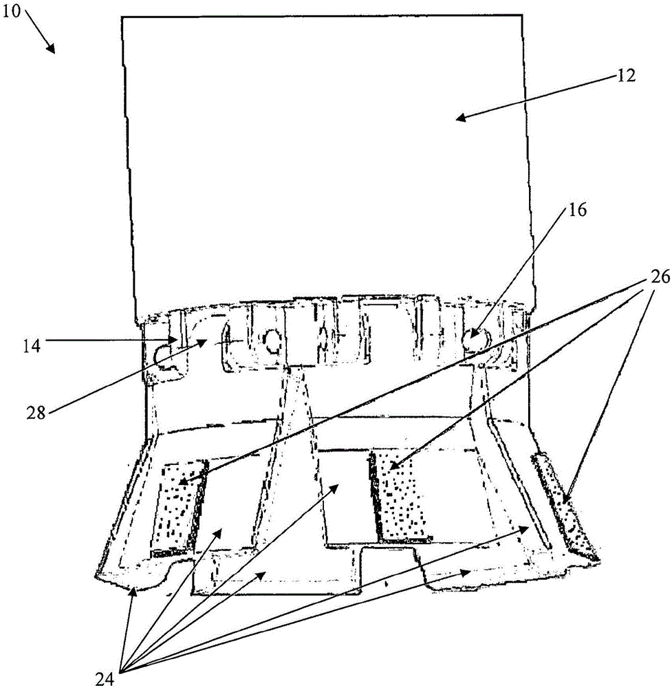
[0041] refer to figure 1 , shows an undercutting tool 10 having a tool body 12 and being connected to six wedges 12 . Connection point 14 on tool body 12 is attached to connection portion 28 of wedge 12 by connection member 16 . The connection members 16 are slightly deformed at the ends to prevent them from loosening from the connection point 14 . The cutting surface 26 is attached to the wedge 12 .

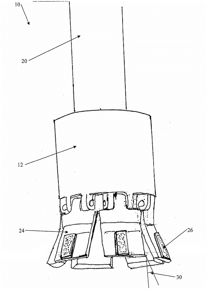
[0042] figure 2 The undercutting tool 10 is shown attached to a shaft 20 . As the undercutting tool 10 rotates, the wedges 24 are pushed outward, increasing the angle 30 between the tool body 12 and the wedges 24 . The angle 30 of the wedge 24, such as figure 2 , would be equivalent to a moderate rotational speed of the undercut tool. Typically, the undercutting tool 10 will be attached to a drill or the like (not shown) and lowered into a hole (not shown), the wedge 24 will be in a retracted position, allowing the undercutting tool 10 to be lowered into the hole (not sh...


PUM


Abstract

An undercutting tool for producing an undercut in a bore, the undercutting tool comprising a tool body, which can be at least partially inserted into the bore that is to be undercut, at least one wedge moveably attached to the tool body and at least one cutting surface. The at least one wedge is displaced outwardly by centrifugal force due to rotation of the undercutting tool. The at least one cutting surface is adapted to cut into the bore that is to be undercut as the at least one wedge is displaced outwardly.

Description

technical field [0001] The present invention relates to undercutting tools. In certain embodiments, the invention relates to undercut tools for creating undercuts in pilot holes in concrete, cement, rock, and the like, although the scope of the invention is not necessarily limited thereto. Background technique [0002] Undercut tools are available in the market and are used to create undercuts in the walls of holes in concrete and the like. [0003] Existing undercutting tools are complex and often have many moving parts to be able to sufficiently undercut the hole by pushing the cutting portion against the hole wall. For example, US Patent 4,502,544 discloses a rotary power tool for reaming a frusto-conical undercut in a cylindrical hole by using a ram to push the cutting blade outward to undercut the wall of the hole. [0004] A problem with existing undercutting tools is that the time it takes to undercut a hole can be relatively long because some of the tools need to b...

Claims


Application Information

Patent Timeline
Patent Type & Authority Patents(China)
IPC IPC(8): B23B51/00B26D1/15E21B7/28B23B51/02B26D1/153E21B7/30B23B51/10B26D1/30E21B10/32B26D1/14B26D3/00
CPCB23B51/0045Y10T408/85E21B10/32B23B2270/04
Inventor 帕特·凯利
Owner OBELIX HLDG
Why Eureka
Try Eureka