Automatic charging and discharging system

An automatic loading and unloading technology, applied in the direction of conveyor objects, furnaces, lighting and heating equipment, etc., can solve the problems of dirty workpieces, labor-intensive, defective workpieces, etc.

Inactive Publication Date: 2013-03-06
SHENZHEN FUTAIHONG PRECISION IND CO LTD
View PDF5 Cites 38 Cited by
  • Summary
  • Abstract
  • Description
  • Claims
  • Application Information

AI Technical Summary

Problems solved by technology

Since the loading and unloading of the workpiece is completely done manually by the operator, it not only consumes a lot

Method used


Image

  • Automatic charging and discharging system
  • Automatic charging and discharging system
  • Automatic charging and discharging system

Examples


Embodiment Construction

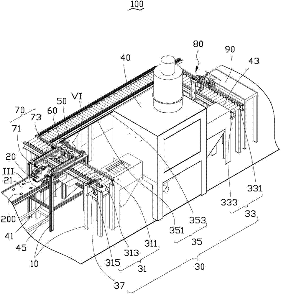
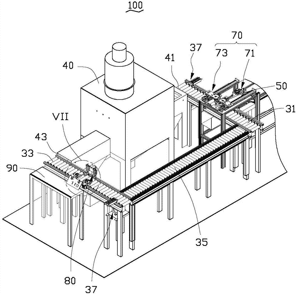
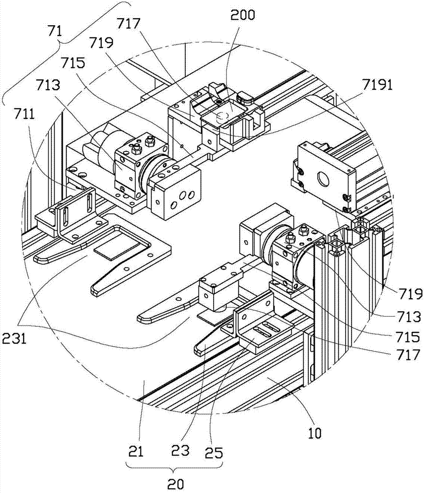
[0016] see figure 1 and figure 2 , The automatic loading and unloading system 100 of the preferred embodiment of the present invention includes a mounting frame 10, a feeding conveying mechanism 20, a roller conveying mechanism 30, a processing device 40, a conveying member 50, a jig positioning mechanism 60, a feeding mechanism 70, Blanking mechanism 80 and blanking table 90. The feeding conveying mechanism 20 is used to transfer the workpiece 200 to be processed to the feeding mechanism 70 and position the workpiece 200 to be processed, and the feeding mechanism 70 grabs and places the workpiece 200 to be processed on the conveying member 50 Above, the roller transfer mechanism 30 transfers the transfer member 50 positioned to be processed to the processing device 40 for corresponding processing, and the roller transfer mechanism 30 then transfers the transfer member 50 to the unloading mechanism 80, and passes through the unloading The mechanism 80 takes out the processe...


PUM


Abstract

The invention discloses an automatic charging and discharging system, which is used for automatically charging workpieces to be machined and automatically discharging machined workpieces. The automatic charging and discharging system comprises a conveyer belt, a roller conveying mechanism, a machining device, a conveying member, a charging mechanism and a discharging mechanism, wherein the conveyer belt is used for conveying a workpiece to be machined to the charging mechanism; the roller conveying mechanism comprises a first conveying section and a second conveying section, and the machining device is connected between the first conveying section and the second conveying section; the charging mechanism is used for sucking the workpiece to be machined from the conveyer belt and positioning the workpiece to be machined on the conveying member; and the first conveying section is used for conveying the conveying member on which the workpiece to be machined is positioned to the machining device to be machined, the second conveying section is used for conveying the conveying member and the machined workpiece to the discharging mechanism, and the discharging mechanism is used for taking the machined workpiece out from the conveying member.

Description

technical field [0001] The invention relates to an automatic feeding and unloading system. Background technique [0002] At present, when performing sandblasting and painting processes on workpieces, the workpiece needs to be positioned on a jig, and then the jigs are placed in a sandblasting machine or a paint booth for corresponding sandblasting or painting treatment. The existing operation method is generally to manually position the workpiece to be processed on the jig by the operator, and then transfer the jig with the workpiece positioned to the sandblasting machine or paint room by a conveying mechanism such as a conveyor belt for corresponding processing, and finally manually Remove the sandblasted or painted workpiece from the fixture. Since the loading and unloading of the workpiece is completely done by the operator, it not only consumes a lot of manpower, but also easily causes defective workpieces, such as scratching or dirtying the workpiece. Contents of the...

Claims


Application Information

Patent Timeline
IPC IPC(8): B65G49/00B65G47/91
Inventor 张高综刘俊余洪伟荣
Owner SHENZHEN FUTAIHONG PRECISION IND CO LTD
Why Eureka
Try Eureka