Winding machine and method for controlling the same

A technology for controlling coils and winding machines, applied in the direction of transportation and packaging, tension measurement, conveying filamentous materials, etc.

Inactive Publication Date: 2013-03-06
GEORG SAHM GMBH & CO KG
View PDF14 Cites 13 Cited by
  • Summary
  • Abstract
  • Description
  • Claims
  • Application Information

AI Technical Summary

Problems solved by technology

But the premise is that conical drums or pressure rollers must be used

Method used


Image

  • Winding machine and method for controlling the same
  • Winding machine and method for controlling the same
  • Winding machine and method for controlling the same

Examples


Embodiment Construction

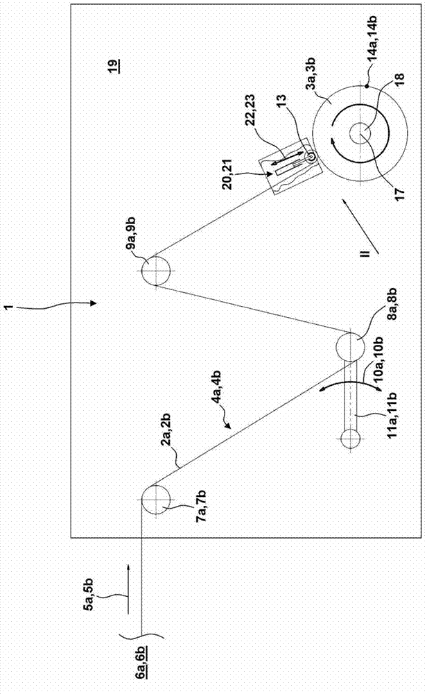
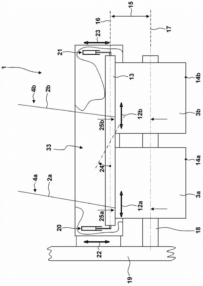
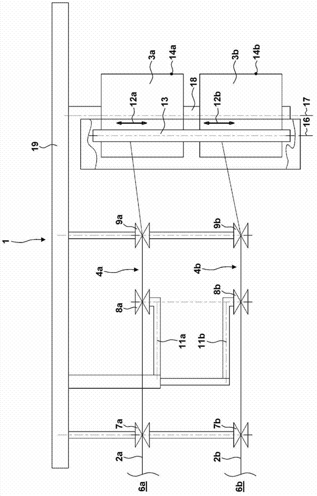
[0045] figure 1 A winder 1 is shown. as in figure 2 with 3 As seen in more detail in Winder 1, windings 2a, 2b are conveyed in parallel to mandrels 3a, 3b via input paths 4a, 4b which run perpendicular to figure 1 staggered in the direction of the drawing. Similar components in the supply path 4 a , 4 b are denoted in parts in the description with the same reference numerals and the additional letter a or b. Of course, it is also possible to use more than the two shown parallel input paths 4 a , 4 b on the winder 1 .

[0046] The path of the windings 2a, 2b through the feeding paths 4a, 4b is firstly explained below with the aid of the winding 2a via the feeding path 4a, wherein the same applies for the winding 2b in the parallel feeding path 4b:

[0047] The windings 2a leave a supply station 6, not shown in detail in the drawing, at a feed speed 5a, 5b. The winding 2 a is deflected in the direction of the movable dancer roller 8 a by means of the stationary first defl...


PUM


Abstract

The invention relates to a method for controlling a winding machine (1). The method involves performing parallel winding of continuously running goods (2a, 2b) to be wound to coils (3a, 3b) that are supported on a common spindle (18). Control signals are produced, and actuators (20, 21) are subjected with the signals, where the actuator changes contact force of a pressure roller (13) at the coils depending on the signals. The signals are provided depending on voltage of the goods to be wound and / or deflection of dancer rollers (8a, 8b). Rotational speed of the coils is controlled depending on the voltage of the goods and / or the deflection of the dancer rollers.

Description

technical field [0001] The invention relates to a method for controlling a winding machine in which a continuously fed winding, in particular yarn, tape, wire, filament, etc., is wound onto two or more mandrels, the The reels are supported on a common shaft. The invention also relates to a winder, by means of which a continuously fed roll is wound in parallel onto a plurality of mandrels. Background technique [0002] In known winding machines, the continuous winding is conveyed from a supply station via an input path in the winding machine to a winding station, the supply station being formed in particular directly by a winding processing device or a winding storage device, in which In the winding station, the winding is processed with or without a sleeve to form a reel supported on a shaft. During winding, the winding is reciprocated on the input path by means of the serial device parallel to the axis, thereby forming a space drum. In order to ensure that the distance b...

Claims


Application Information

Patent Timeline
Patent Type & Authority Applications(China)
IPC IPC(8): B65H54/52
CPCB65H54/20B65H54/52B65H59/385B65H54/22B65H54/70B65H59/38B65H63/028B65H59/00B65H59/40B65H61/00G01L5/10
Inventor C·格克
Owner GEORG SAHM GMBH & CO KG
Why Eureka
Try Eureka