High-strength louver blade component
A louver, high-strength technology, applied in the direction of louvers/movable grilles, building components, door/window protection devices, etc., can solve the problems of anti-theft, unsatisfactory wind pressure resistance, and inconvenience for users in daily life, and achieve anti-theft performance Good, simple structure, good wind pressure resistance
- Summary
- Abstract
- Description
- Claims
- Application Information
AI Technical Summary
Problems solved by technology
Method used
Image
Examples
Embodiment 1
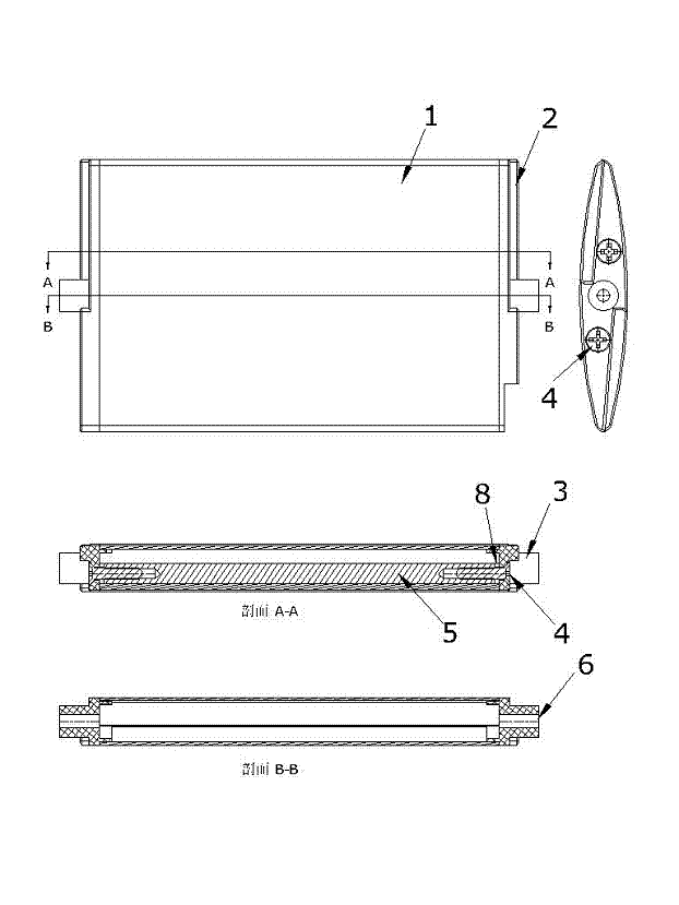
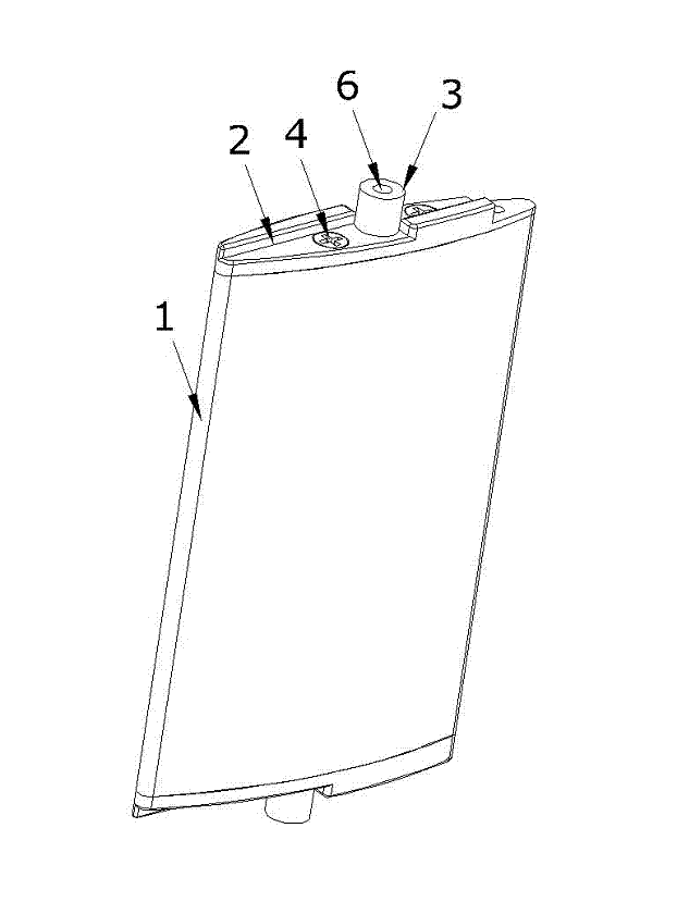
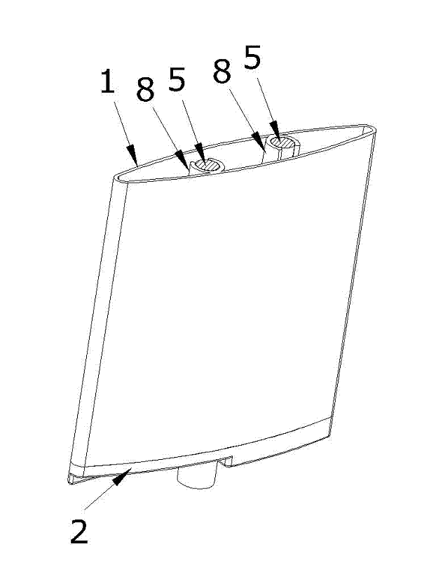
[0024] Example 1: figure 1 , figure 2 , image 3 A diagram of this example is given. see figure 1 , figure 2 , image 3 , the present invention mainly includes louvers 1 , blade covers 2 , raised shafts 3 , screws 4 , metal components 5 , threaded holes 6 , and semicircular ribs 8 . It is characterized in that a number of metal components 5 are arranged inside the louver 1, and the metal components 5 are clamped and positioned by the semicircular ribs 8 inside the louver 1, and the two ends of the louver 1 are provided with a blade cover 2, and the blade cover 2 is provided with The protruding rotating shaft 3 integrated with itself is provided with a threaded hole 6. In order to further strengthen the strength of the louver assembly and fasten the blade cover 2, it can be provided on one or both sides of the blade cover 2. For the screws 4 of the solid blade cover 2, the screws 4 act on the metal components inside the louvers 1.
[0025] Commonly used materials for t...
Embodiment 2
[0032] Example 2: Figure 4 , Figure 5 , Figure 6 A diagram of this example is given. see Figure 4 , Figure 5 , Figure 6 , the present invention mainly includes a louver 1, a blade cover 2, a raised shaft 3, a screw 4, a metal member 5, a threaded hole 6, and a circular step 7. Embodiment 2 is basically the same as Embodiment 1, except that the semicircular rib 8 on the inner side of the louver 1 is omitted in order to save material, and a circular step 7 is provided on the blade cover 2 for clamping and Position metal member 5.
[0033] the above Figure 7 It is a schematic diagram of the application of the present invention to louvered doors and windows, which is a relatively conventional one, and is not intended to limit the application of the present invention to other structural forms of louvered doors, louvered curtain walls or louvers.
PUM
 Abstract
Description
Claims
Application Information
 - R&D
- Intellectual Property
- Life Sciences
- Materials
- Tech Scout
- Unparalleled Data Quality
- Higher Quality Content
- 60% Fewer Hallucinations
Browse by: Latest US Patents, China's latest patents, Technical Efficacy Thesaurus, Application Domain, Technology Topic, Popular Technical Reports.
© 2025 PatSnap. All rights reserved.Legal|Privacy policy|Modern Slavery Act Transparency Statement|Sitemap|About US| Contact US: help@patsnap.com


