Coherent factor adjusting system in deep ultraviolet lithography lighting system

A lighting system and deep ultraviolet light technology, applied in the direction of microlithography exposure equipment, photolithography process exposure device, etc., can solve the problems of affecting the exposure efficiency of lithography machines, increasing the volume of the lighting system, increasing the cost, etc., and achieving small space , reduced volume, and high control precision

Active Publication Date: 2014-11-26
INST OF OPTICS & ELECTRONICS - CHINESE ACAD OF SCI
View PDF4 Cites 0 Cited by
  • Summary
  • Abstract
  • Description
  • Claims
  • Application Information

AI Technical Summary

Problems solved by technology

[0008] However, for a longer dodging rod, it takes a lot of space to replace the end face of the dodging rod, which increases the size and cost of the lighting system
The longer the length of the dodging rod, the higher the precision of the stepper motor required to change the position of the dodging rod, and the longer the time required for the process of changing the position, it is easy to affect the exposure efficiency of the lithography machine

Method used


Image

  • Coherent factor adjusting system in deep ultraviolet lithography lighting system
  • Coherent factor adjusting system in deep ultraviolet lithography lighting system
  • Coherent factor adjusting system in deep ultraviolet lithography lighting system

Examples


Embodiment Construction

[0027] The specific implementation manner of the present invention will be further described in detail below in conjunction with the accompanying drawings and specific examples.

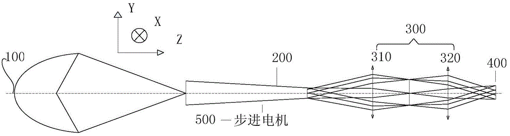
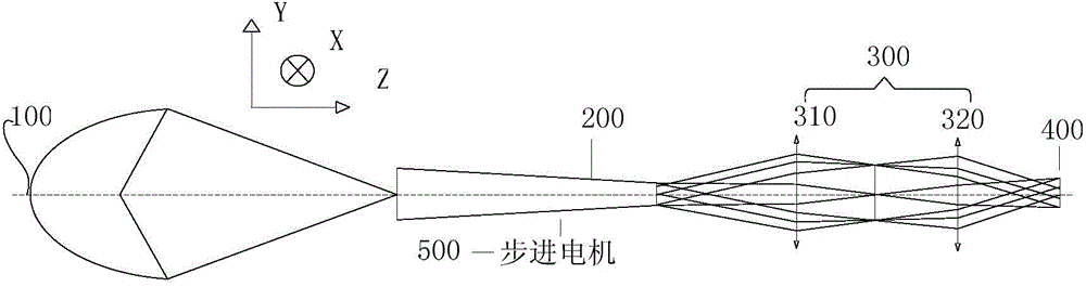
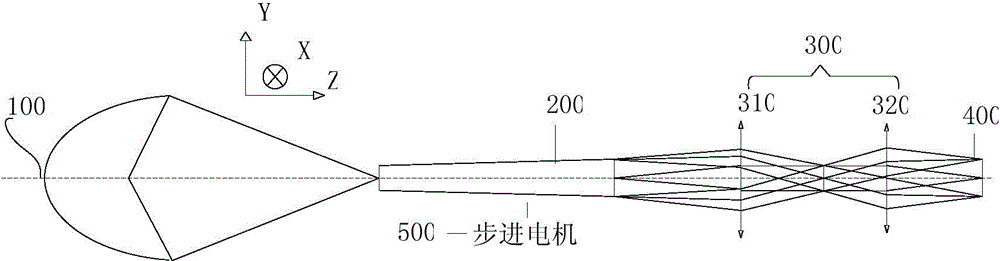
[0028] The invention can realize multi-level coherence factor conversion with a simple method, reduce the space of the lighting system, and increase the exposure efficiency.

[0029] The present invention uses the control device to control the coherence factor of a series of homogenization rods with the same exit port diameter but different entrance port diameters to adjust the system. The control device only needs to rotate around the rotation axis parallel to the optical axis of the lighting system to achieve multi-level values. Aperture, that is, the change in coherence factor. This method requires less space than the method of changing the numerical aperture by exchanging the end face position of a single dodging rod. The control device is driven by a high-precision rotary table, which can achie...


PUM


Abstract

The invention discloses a coherent factor adjusting system in a deep ultraviolet lithography lighting system. The coherent factor adjusting system comprises a converging lens group, light-homogenized robs, a control device and a lighting field, wherein the converging lens group is arranged on a lighting light path of the lighting system and is responsible for converging the light to an appointed position; the light-homogenized robs are arranged on the light path of the converging lens group of the system; the light converged by the converging lens group enters through incidence ends of the light-homogenized robs and exit through exit ends of the light-homogenized robs; the control device is used for fixing a plurality of light-homogenized robs with different aperture ratios, and is provided with a rotating shaft which is parallel to the optical axis of the lighting system; the control device rotates around the rotating shaft so as to adjust the positions of the light-homogenized robs, so that appointed light-homogenized robs are put in the light path of the lighting system to join in adjusting coherent factors of the lighting system; the control device is driven by a high precision rotary table; relay lenses are arranged on the exit light path of the light-homogenized robs; and the lighting field is arranged on the exit light path of the relay lenses. By utilizing the coherent factor adjusting system, the coherent factors of a system can be adjusted, or the design complexity of a varifocus lens can be simplified, so that the purposes of simplifying the structure and reducing the cost are achieved.

Description

technical field [0001] The invention relates to the field of lithography, in particular to a system for adjusting coherence factor in a deep ultraviolet lithography illumination system. Background technique [0002] Optical projection lithography is an optical exposure process that uses the principle of optical projection imaging to transfer the integrated circuit (IC) pattern on the reticle to the rubber-coated silicon wafer in a step-by-step or step-and-scan manner. . [0003] According to different exposure requirements when the lithography machine is actually working, different numerical apertures or coherence factors are required on the silicon wafer. [0004] Existing technologies mainly use wedge-shaped homogenization rods to obtain different exposure fields of view, numerical apertures or coherence factors. It is also possible to use a wedge-shaped homogenizing rod to cooperate with a zoom lens group to obtain different exposure fields of view, numerical apertures ...

Claims


Application Information

Patent Timeline
Patent Type & Authority Patents(China)
IPC IPC(8): G03F7/20
Inventor 卢亮张海波廖志杰林妩媚邢廷文甘大春何毅
Owner INST OF OPTICS & ELECTRONICS - CHINESE ACAD OF SCI
Why Eureka
Try Eureka