

Heat-producing fixing belt and image forming apparatus using the same
A technology of fixing belt and heat generating layer, which is applied to electric heating device, electric recording process applying charge pattern, equipment of electric recording process applying charge pattern, etc.
- Summary
- Abstract
- Description
- Claims
- Application Information
AI Technical Summary
Problems solved by technology
Method used
Image

Examples
Embodiment 1
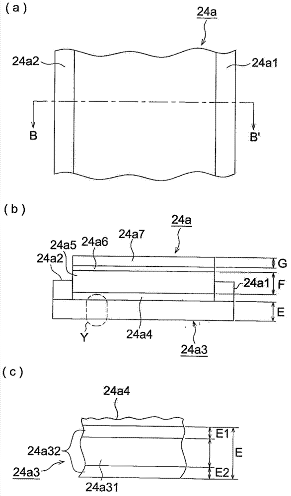
[0155] Created using the method shown below image 3 Heat-generating fixing belts of the structure shown, and designated as sample Nos. 101 to 109.
[0156] (Preparation for loop weaving)
[0157] Toray woven fabrics using carbon fibers shown in Table 1 were sewn together with carbon fibers to obtain endless woven fabrics.
[0158] [Table 1]
[0159]
[0160] 1-1 and 1-2 were produced by sewing cloth into a loop. 1-3~1-7 are made of carbon fiber weaving into cylindrical cloth. In Table 1, the thickness represents the equivalent image 3 The thickness of 24a31 in (c).
[0161] The thickness of carbon fiber shows the value measured based on JIS L0101-1978.
[0162] The fiber density of the woven fabric represents a value obtained by visually measuring the number of fibers in a range of 25 mm×25 mm. The thickness of the woven fabric represents a value obtained by measuring a cross-section with a reflection optical microscope.
[0163] (Wrapping of woven fabric with po...
PUM
 Abstract
Description
Claims
Application Information