Target identification method based on interferogram matching

Inactive Publication Date: 2013-03-06
XI'AN INST OF OPTICS & FINE MECHANICS - CHINESE ACAD OF SCI
View PDF1 Cites 2 Cited by
  • Summary
  • Abstract
  • Description
  • Claims
  • Application Information

AI Technical Summary

Problems solved by technology

As we all know, the Fourier transform is a time-consuming calculation. Even if the fa

Method used


Image

  • Target identification method based on interferogram matching
  • Target identification method based on interferogram matching
  • Target identification method based on interferogram matching

Examples


Embodiment Construction

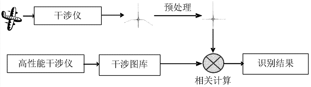
[0019] The advantage of interferogram matching is that no spectral restoration is performed, and the process of Fourier transform is omitted. The disadvantage of this is that the target spectral distribution cannot be obtained, and direct spectral analysis cannot be performed. However, for some application areas such as object recognition, direct analysis of spectra is not necessarily required. Like the spectral identification technology, the interferogram matching technology needs to first establish an interferogram library containing the desired target.

[0020] The present invention provides a kind of target recognition method based on interferogram matching, and this method comprises the following steps:

[0021] 1) Establish the desired target interferogram database:

[0022] When building an interferogram library, a Fourier transform spectrometer with a high signal-to-noise ratio should be used to collect the interferogram, which should be used as a data source after p...


PUM


Abstract

The invention relates to a target identification method based on interferogram matching. The method includes the steps of firstly, establishing an expected target interferogram database; secondly, acquiring a target interferogram to be identified; and thirdly, identifying the target interferogram to be identified, which is obtained in the step 2, and the expected target interferogram database established in the step 1 to identify a target to be identified. The target identification method based on interferogram matching is high in identification speed and can identify the target.

Description

technical field [0001] The invention belongs to the field of spectrum application, and relates to a target recognition method, in particular to a target recognition method based on interferogram matching. Background technique [0002] In applications such as spectral military and remote sensing, it is very important to realize target recognition through spectral matching. At present, the commonly used spectral matching methods include spectral binary code matching, correlation coefficient measurement and other methods, and people have also developed classification and recognition methods based on artificial neural networks. When using these methods, the spectral distribution of the target must be obtained first, and then identification based on the spectrum is carried out. [0003] Interferometric spectral imaging technology has many advantages, but the interferogram data obtained by the instrument must be transformed by Fourier to obtain the spectral distribution of the ta...

Claims


Application Information

Patent Timeline
IPC IPC(8): G06K9/62
Inventor 杨晓许周泗忠相里斌罗俊萍
Owner XI'AN INST OF OPTICS & FINE MECHANICS - CHINESE ACAD OF SCI
Why Eureka
Try Eureka