Ultrasonic diagnosis device

A diagnostic device, ultrasonic technology, applied in the direction of acoustic wave diagnosis, infrasonic wave diagnosis, ultrasonic/sonic wave/infrasonic wave diagnosis, etc.

Active Publication Date: 2013-03-06
TOSHIBA MEDICAL SYST CORP
View PDF8 Cites 10 Cited by
  • Summary
  • Abstract
  • Description
  • Claims
  • Application Information

AI Technical Summary

Problems solved by technology

[0006] The object of the present invention is to provide an ultrasonic diagnostic device capable of displaying Doppler waveforms on a speed display scale that can be easily observed by the operator without troublesome operations.

Method used


Image

  • Ultrasonic diagnosis device
  • Ultrasonic diagnosis device
  • Ultrasonic diagnosis device

Examples


no. 1 Embodiment approach )

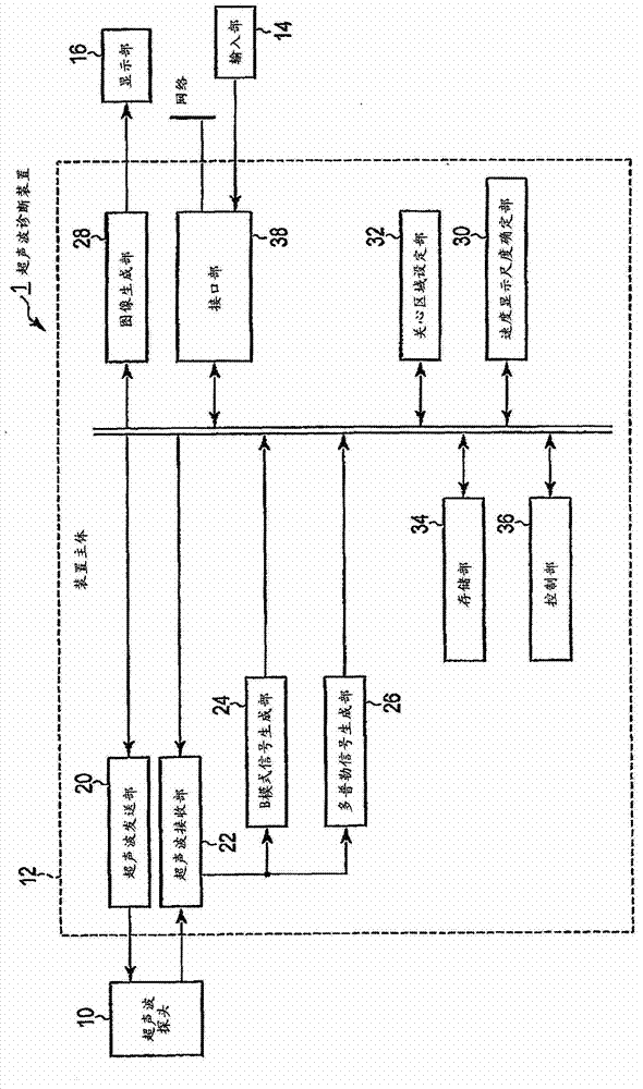
[0031] figure 1 A block configuration diagram of the ultrasonic diagnostic apparatus 1 according to the first embodiment is shown. As shown in the figure, the ultrasonic diagnostic apparatus 1 has an ultrasonic probe 10, an apparatus main body 12, and an input unit 14 connected to the apparatus main body 12 for taking various instructions, commands, and information from an operator into the apparatus main body 12. , and the display unit 16. In addition, the ultrasonic diagnostic apparatus 1 may be connected to a biological signal measurement unit (not shown) represented by an electrocardiometer, a heart sound monitor, a pulse meter, and a respiration sensor, and a network via the interface unit 38 .

[0032] The ultrasonic probe 10 has piezoelectric vibrators such as piezoelectric ceramics as acoustic / electric reversible conversion elements. A plurality of piezoelectric vibrators are arranged in parallel at the front end of the ultrasonic probe 10 . In addition, a case wher...

no. 2 Embodiment approach )

[0084] Hereinafter, a second embodiment will be described with reference to the drawings.

[0085] Figure 9 It is a configuration diagram showing the configuration of the ultrasonic diagnostic apparatus according to the second embodiment. The difference from the first embodiment is that the filter characteristics of the filter included in the Doppler signal generation unit 26 are changed according to the freezing operation of the operator via the input unit 14 .

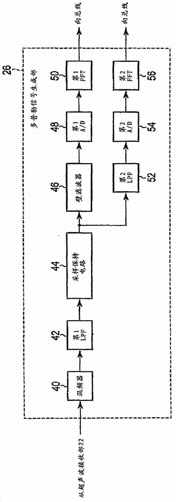
[0086] The device main body 12 includes a filter changing unit 39 in addition to the components of the first embodiment. First, refer to Figure 10 , the Doppler signal generator 26 will be described. Figure 10 It is a configuration diagram showing the configuration of the Doppler signal generator 26 of the ultrasonic diagnostic apparatus 1 according to the present embodiment. The Doppler signal generator 26 has a mixer (mixer) 40 , a low-pass filter (hereinafter referred to as LPF) 41 , a sample hold (Sample H...

no. 3 Embodiment approach )

[0110] Hereinafter, a third embodiment will be described with reference to the drawings.

[0111] Figure 14 It is a configuration diagram showing the configuration of the ultrasonic diagnostic apparatus according to the third embodiment. The difference from the first and second embodiments is that a plurality of range gates are set in the ROI based on pixel values ​​in the ROI, and a Doppler image is generated for each of the set range gates. The device main body 12 includes a range gate specifying unit 37 in addition to the components of the first embodiment.

[0112] The region-of-interest setting unit 32 sets an ROI on the B-mode image displayed on the display unit 16 based on an operator's instruction input through the input unit 14 .

[0113] The range gate specifying unit 37 specifies the positions of a plurality of range gates within the ROI based on the pixel values ​​within the ROI. The position of the Range gate is set in an azimuth direction. For simplicity of ...


PUM


Abstract

An ultrasonic diagnosis device characterized by the provision of the following: an ultrasound probe; an ultrasound transmission unit that transmits ultrasound towards a subject through the ultrasound probe; an ultrasound reception unit that generates a received signal on the basis of reflected waves corresponding to the aforementioned ultrasound; a Doppler-signal generation unit that, on the basis of said received signal, generates a first Doppler signal and a second Doppler signal, said first Doppler signal resulting from biological motion in a prescribed direction inside a region of interest and said second Doppler signal resulting from motion that is slower than the motion inside the region of interest; a velocity-display scale determination unit that determines a first velocity-display scale on the basis of a velocity distribution range from the first Doppler signal and determines a second velocity-display scale on the basis of a velocity distribution range from the second Doppler signal; an image generation unit that generates a first Doppler image on the basis of the first Doppler signal and generates a second Doppler image on the basis of the second Doppler signal; and a display unit that displays the first Doppler image at the first velocity-display scale and the second Doppler image at the second velocity-display scale.

Description

technical field [0001] Embodiments of the present invention relate to an ultrasonic diagnostic apparatus having a Doppler function. Background technique [0002] Conventionally, in an ultrasonic diagnostic apparatus, in order to determine the presence or absence of arteriosclerosis, the phase shift between the blood flow velocity and the movement velocity of the blood vessel wall is evaluated using a tissue analysis dedicated mode. Unnecessary signals mixed into the Doppler signal are removed by filtering according to the setting of the displayed velocity scale (hereinafter referred to as the velocity display scale). Doppler signals obtained from different objects in the function of displaying velocity value information and time phases related to different positions in the subject as different azimuth directions together (hereinafter referred to as dual Doppler function) Display with the same speed display range. [0003] However, in the conventional dual-Doppler function,...

Claims


Application Information

Patent Timeline
Patent Type & Authority Applications(China)
IPC IPC(8): A61B8/08A61B8/06
CPCA61B8/461A61B8/488G01S7/52073A61B8/08A61B8/14A61B8/06A61B8/5207A61B8/5246G01S7/52074A61B8/0891G01S7/52066G01S15/8979A61B8/463A61B8/466
Inventor 佐佐木琢也
Owner TOSHIBA MEDICAL SYST CORP
Why Eureka
Try Eureka