Stretcher compartment
A stretcher bin and bin body technology is used in vehicle rescue, medical transportation, transportation and packaging, etc. It can solve problems such as poor safety and reliability, and achieve the effects of reducing labor intensity, simple structure, flexible and reliable action
- Summary
- Abstract
- Description
- Claims
- Application Information
AI Technical Summary
Problems solved by technology
Method used
Image

Examples
Embodiment Construction
[0016] The present invention will be described in further detail below in conjunction with the accompanying drawings.
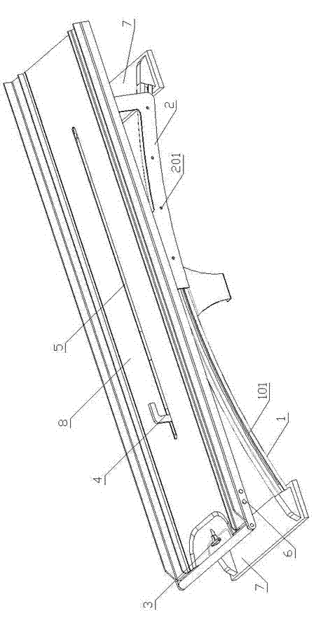
[0017] figure 1 It is a three-dimensional schematic diagram of the stretcher compartment of the present invention. The two ends of the two arc-shaped rails 1 are fixed on the fixed plate 7 and kept parallel to each other. Curved slideways 101 are provided on the outer surfaces of the two curved rails. Such as figure 1 , 3 As shown, arc slides 2 are respectively arranged on both sides of the back of the warehouse body, and four slide blocks or pulleys 201 are arranged on the inside of the arc slides, and the slide blocks or pulleys of the arc slides are nested in the slideway of the arc track. Through the sliding of the slider or the pulley of the arc-shaped slide plate in the slideway of the arc-shaped track, the purpose of tilting and swinging the warehouse body forward and backward is achieved.
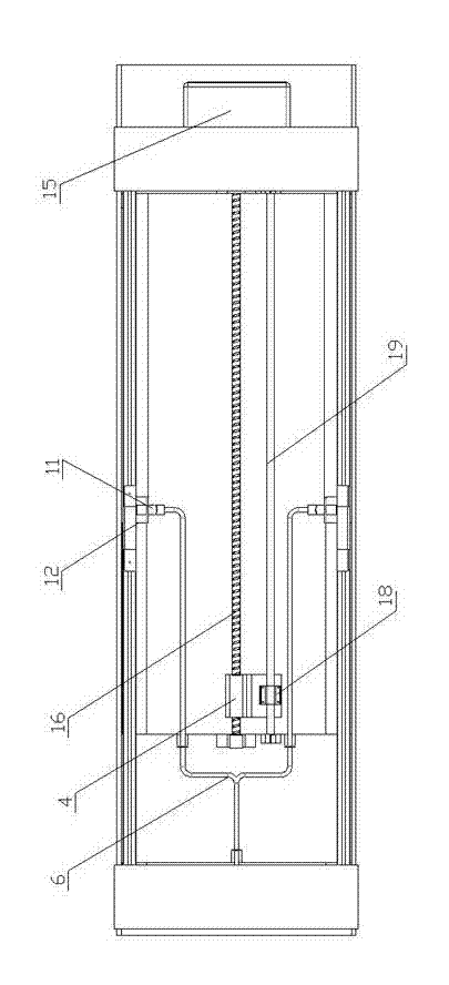
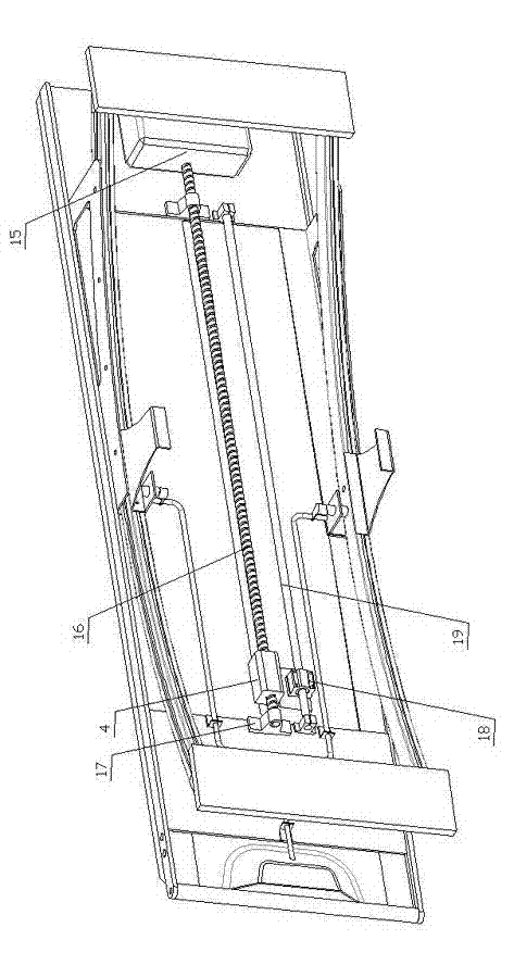
[0018] Such as image 3 , 5 , 6, the arc top of the ar...
PUM
 Abstract
Description
Claims
Application Information
 - Generate Ideas
- Intellectual Property
- Life Sciences
- Materials
- Tech Scout
- Unparalleled Data Quality
- Higher Quality Content
- 60% Fewer Hallucinations
Browse by: Latest US Patents, China's latest patents, Technical Efficacy Thesaurus, Application Domain, Technology Topic, Popular Technical Reports.
© 2025 PatSnap. All rights reserved.Legal|Privacy policy|Modern Slavery Act Transparency Statement|Sitemap|About US| Contact US: help@patsnap.com