
Structure of hydraulic press

A hydraulic press and liquid flushing technology, which is applied to forging presses, forging presses, forging/pressing/hammer devices, etc., can solve the problems of large energy consumption and complex structure, and achieve the effect of less energy consumption, complex structure and simple structure

Inactive Publication Date: 2013-03-13
梅利
View PDF0 Cites 0 Cited by
  • Summary
  • Abstract
  • Description
  • Claims
  • Application Information

AI Technical Summary

Problems solved by technology

[0003] The purpose of the present invention is to provide a hydraulic press structure, which overcomes the defects of complex structure and large energy consumption in existing hydraulic presses

Method used


Image

  • Structure of hydraulic press

Examples


Embodiment Construction

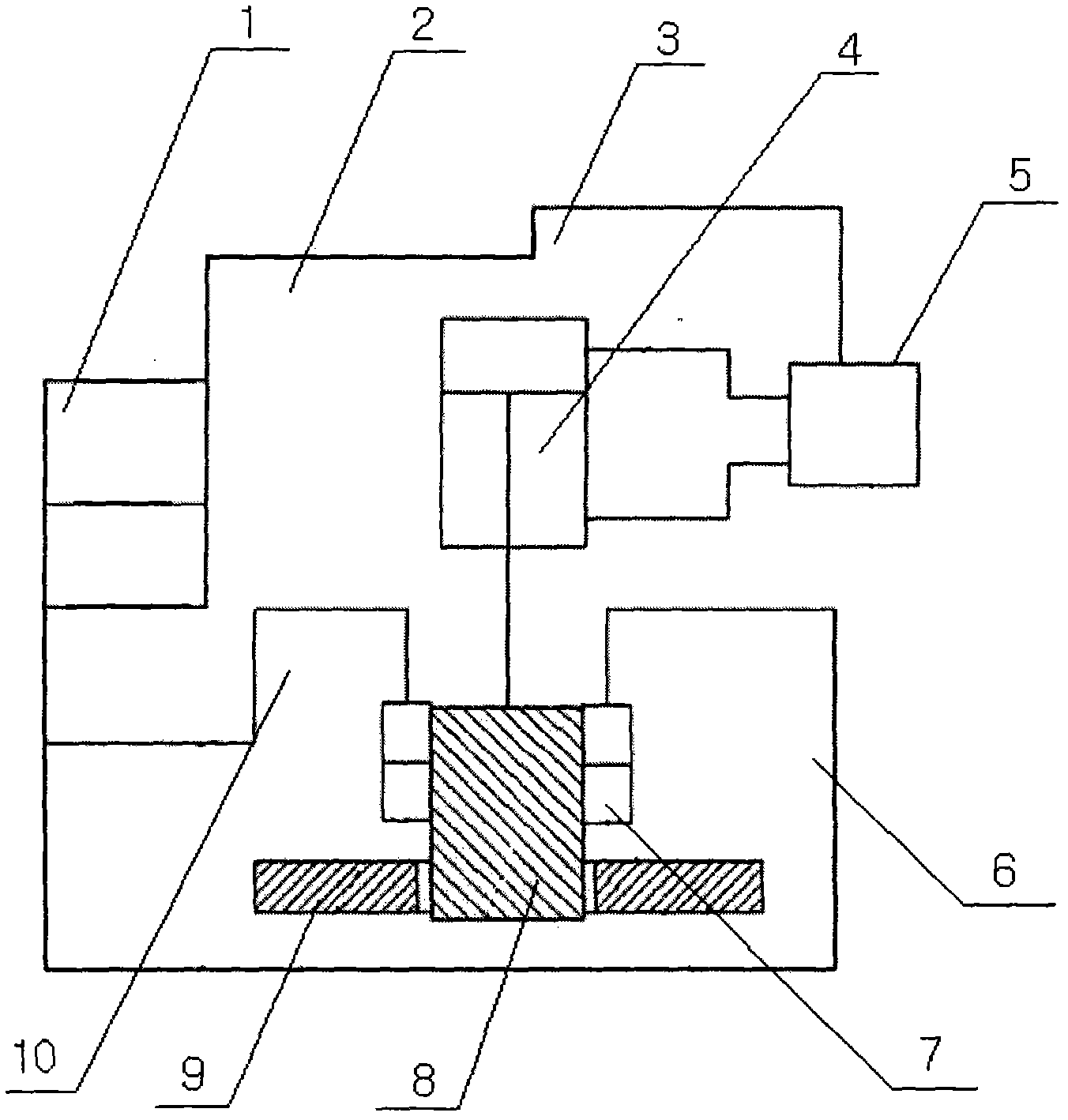
[0008] The structure of the hydraulic press has a liquid flushing cylinder (10), which is connected with the blank holder oil cylinder (7) through the slide block (8), and a blank blank slide block ( 9), the blank holder slider (9) supplies the flushing cylinder (10) from the blank holder cylinder (7) through the oil tank (6) and the slider (8), and the main oil cylinder ( 4), the main oil cylinder (4) is connected with the host system (5), the host system (5) is connected with the flow door (3), the flow door (3) is connected with the two-way control door (2), and the two-way control door (2) Connect with control door (1), and control door (1) is installed on the side surface of flushing cylinder (10) and the lower end of two-way control door.


PUM


Abstract

The invention discloses a structure of a hydraulic press. A purging tube is connected with a side pressing oil cylinder by a slider, side pressing sliders are arranged at two sides of the slider, the side pressing sliders are supplied to the purging tube from the side pressing oil cylinder through an oil tank and the slider, the upper part of the slider is connected with a main oil cylinder which is connected with a main hydraulic press system, the main hydraulic press system is connected with a flowing door, two-way control doors on the flowing door are connected and are connected with a control door, and the control door is arranged on the side surface of the purging tube and at the lower end of the two-way control door. Due to the adoption of the scheme, the structure of the hydraulic press is simple, low in equipment manufacturing cost, and less in energy consumption, and the defects that the structure is complicated and the energy consumption is larger can be effectively overcome.

Description

technical field [0001] The invention relates to a hydraulic press, in particular to a hydraulic press structure, and belongs to the technical field of forging equipment. Background technique [0002] The hydraulic press is an important equipment for the metal material stretching process. In the design and manufacture of the power of the current hydraulic press, two sets of hydraulic systems driven by independent power sources are used to drive the main slider and the blank holder slider respectively. Therefore, there are not only The structure is complicated, and there is also the defect that energy consumption is relatively large. Contents of the invention [0003] The object of the present invention is to provide a structure of a hydraulic press to overcome the defects of complex structure and large energy consumption in the existing hydraulic press. [0004] In order to achieve the above object, the technical solution adopted by the present invention is: the structure ...

Claims


Application Information

Patent Timeline
Patent Type & Authority Applications(China)
IPC IPC(8): B21J9/02
Inventor 梅利
Owner 梅利
Learn More