
Plate shearing machine with multiple shearing speeds

A technology for shearing machines and braking motors, applied in shearing equipment, shearing devices, metal processing equipment, etc., can solve problems such as difficult maintenance, easy oil leakage of hydraulic shearing machines, single shearing speed of shearing machines, etc.

Inactive Publication Date: 2013-03-13
张安心 +1
View PDF5 Cites 0 Cited by
  • Summary
  • Abstract
  • Description
  • Claims
  • Application Information

AI Technical Summary

Problems solved by technology

[0002] At present, the shearing machines mainly used in the market are Q12 hydraulic shearing machine, Q11 mechanical shearing machine and Q11DK electric control shearing machine. They are the mainstream products selected by customers in production, and hydraulic shearing machines are prone to oil leakage. , the seals are easily damaged, maintenance is difficult, the mechanical shearing machine is noisy, the clutch part is easy to wear, and it is difficult to maintain, and the three types of hydraulic, mechanical, and electronic control shearing machines all have a single shearing speed

Method used


Image

  • Plate shearing machine with multiple shearing speeds
  • Plate shearing machine with multiple shearing speeds
  • Plate shearing machine with multiple shearing speeds

Examples


Embodiment

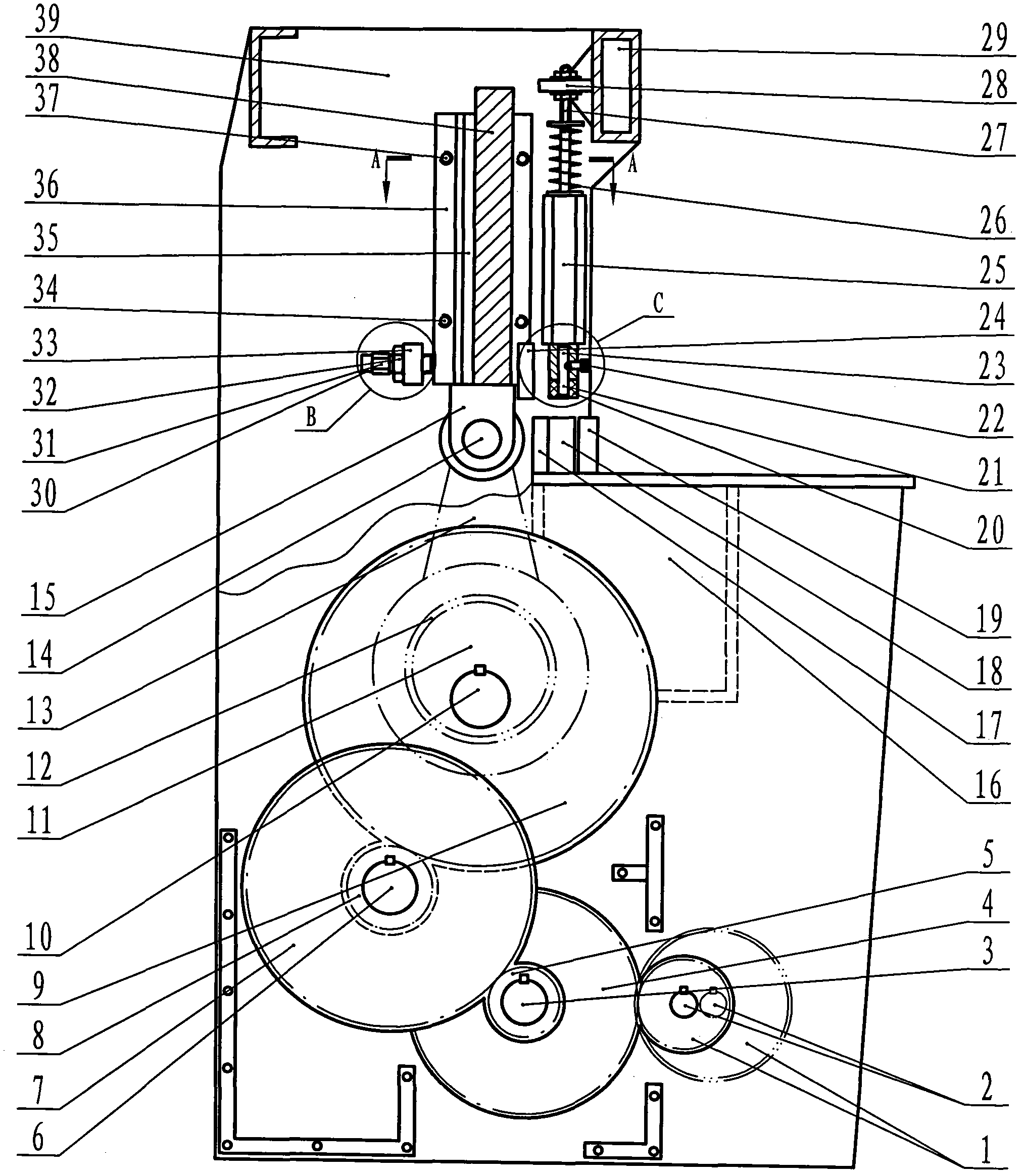
[0024] Example: in figure 1 Among them, the primary small gear (1) on the brake motor (2) drives the primary large gear (4) through the secondary small gear (5) on the primary shaft (3) to drive the secondary large gear (7) The third-stage pinion (8) on the second-stage shaft (6) drives the third-stage large gear (9) to drive the main shaft (10) to rotate the eccentric wheel (11) and the composite sleeve (12) to slide circularly, and there is a chain outside the composite sleeve Bar (13) pulls upper knife rest ear (15) by bearing pin (14) and makes upper blade (24) on the upper knife rest (38) move up and down and lower blade (17) on the lower knife rest (16) realizes cutting. cut function.

[0025] exist figure 2 Among them, the centering bolt (37) is the centering and fastening part of the sliding arm seat (36) circle; the locking bolt (34) is the locking part of the sliding arm seat (36).

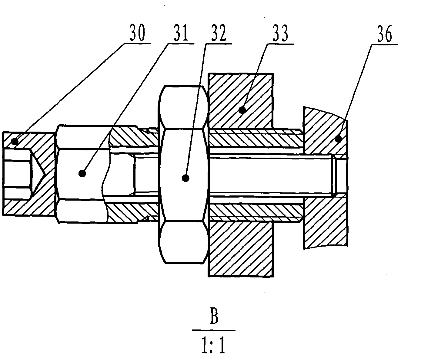
[0026] exist image 3 Among them, the bolt (30) can be tightened back to the sl...


PUM


Abstract

The invention relates to a novel plate shearing machine with multiple shearing speeds. The novel plate shearing machine comprises an electric appliance part, a brake motor, a three-stage gear speed-variable transmission device and a machine body part, wherein the electric appliance part is used for commanding the brake motor to drive a main shaft to rotate through the three-stage gear speed variation, and a chain rod arranged on the outer side of a composite sleeve of an eccentric wheel pulls an upper cutter holder to move vertically, so as to realize shearing purposes. The novel plate shearing machine has the advantages that 1, the torque is increased through the three-stage gear speed variation so as to solve the requirement of shearing power, a standby one-stage small gear of which the number of variable teeth is changed is displaced along with the brake motor so as to realize the requirement of multiple shearing speeds, and the brake motor operates during shearing and stands during non-shearing so as to save energy; 2, the back part of a sliding arm seat of the upper cutter holder is provided with a fixing seat which is matched with a tightening bolt, a thrust nut and a locking nut for use, then the lower end of the sliding arm seat can move to the left and right, and an upper cutter blade and a lower cutter blade are adjusted to a reasonable gap according to requirements so as to reduce burrs of the sheared plates; and 3, a plate pressing structure is provided with a leg pressing shaft so as to avoid the impact by the sheared plate, and a plastic sleeve of the leg pressing shaft has no scratch on the sheared plate.

Description

Technical field [0001] The invention relates to a new sheet metal shearing machine, that is, a multi-shear speed shearing machine. Background technique [0002] At present, the shearing machines mainly used in the market are Q12 hydraulic shearing machine, Q11 mechanical shearing machine and Q11DK electric control shearing machine. They are the mainstream products selected by customers in production, and hydraulic shearing machines are prone to oil leakage. , Seals are easily damaged, maintenance is difficult, mechanical shears are noisy, clutch parts are easy to wear, difficult to maintain, and the three types of hydraulic, mechanical, and electronically controlled shears all have a single shear speed. Contents of the invention [0003] The purpose of the present invention is to provide a new multi-shear speed shearing machine, which adopts a three-stage speed change gear in the structural design, integrates the deceleration and transmission, and replaces the reducer and ...

Claims


Application Information

Patent Timeline
IPC IPC(8): B23D15/12B23D15/08
Inventor 方庆
Owner 张安心
Learn More