
Clamping positioning device for finish machining aero-engine turbine blade

A technology for aero-engine and turbine blades, applied in positioning devices, metal processing equipment, metal processing machinery parts, etc., to achieve the effects of controlling blade processing accuracy, improving positioning accuracy, and not easy to loosen

Active Publication Date: 2013-03-13
AECC AERO SCI & TECH CO LTD
View PDF5 Cites 25 Cited by
  • Summary
  • Abstract
  • Description
  • Claims
  • Application Information

AI Technical Summary

Problems solved by technology

[0005] Aiming at the problems existing in the prior art of fixing blades by pouring low-melting point alloys in square boxes, the purpose of the present invention is to provide a device for positioning and clamping blades by means of mechanical clamping to complete the finishing of blade tenons. In order to fundamentally solve various problems and troubles in removing the residual alloy on the surface of the airfoil and the alloy in the cavity of the airfoil

Method used


Image

  • Clamping positioning device for finish machining aero-engine turbine blade
  • Clamping positioning device for finish machining aero-engine turbine blade
  • Clamping positioning device for finish machining aero-engine turbine blade

Examples


Embodiment 1

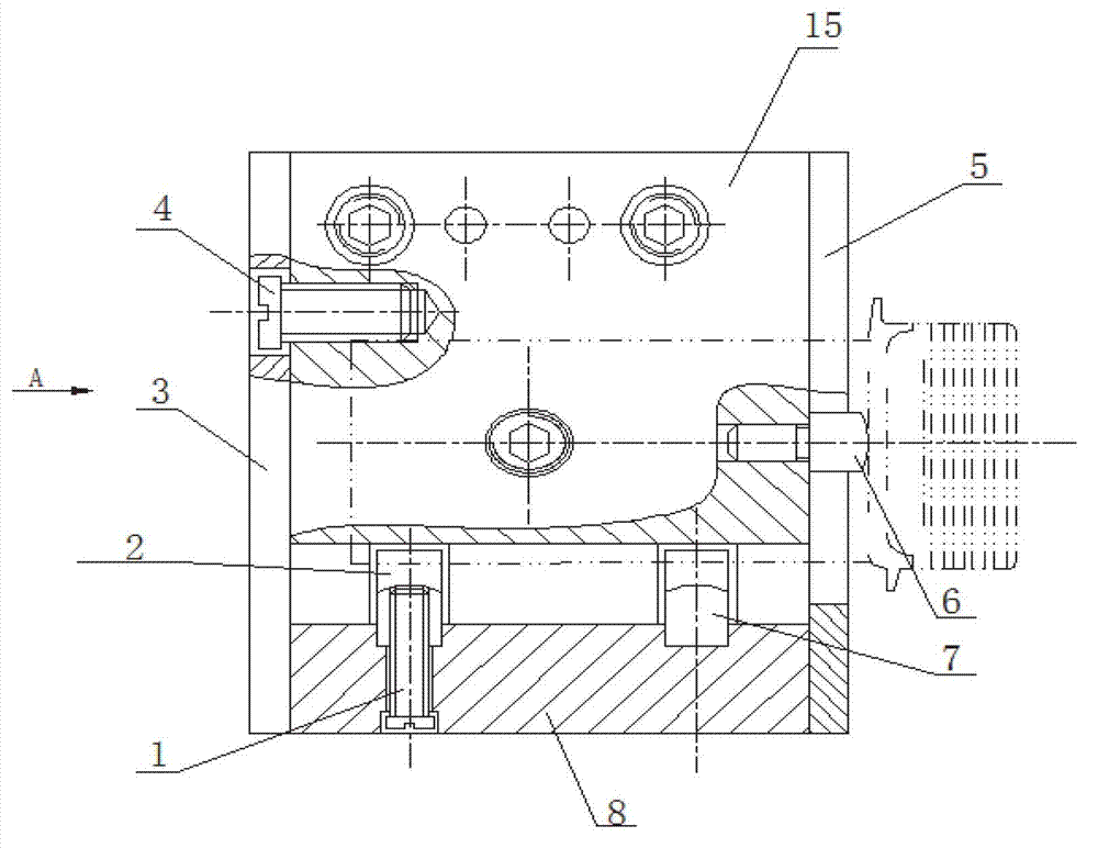
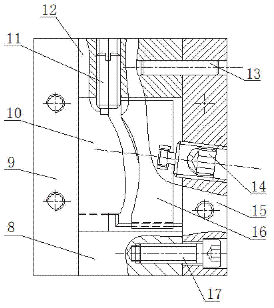
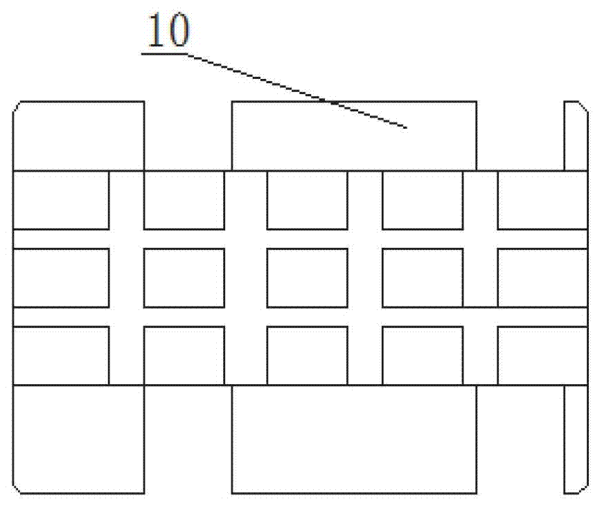
[0024] The clamping and positioning device used for finishing the tenon of the turbine blade of the aero-engine in this embodiment has a structure as attached Figures 1 to 4 As shown, the composition includes a frame composed of front cover plate 15, rear cover plate 9, left cover plate 3, right cover plate 5, upper cover plate 12 and lower cover plate 8 through connecting screws 17 and connecting positioning pins 13, etc. The right cover plate 5 is designed with an opening for placing the blade body into the frame and a positioning pin 6 for axially positioning the blade. The axial positioning of the blade is realized by pressing the end of the positioning pin against the edge plate surface between the blade body and the tenon. . The back positioning and pressing block 16 that matches the profile of the back of the airfoil in the frame can be adjusted on the front cover 15 in the pressing direction through the adjusting pressing screw 14 arranged on the front cover, and is a...


PUM


Abstract

The invention discloses a clamping positioning device for finish machining an aero-engine turbine blade, and the clamping positioning device comprises a framework consisting of a front cover plate, a rear cover plate, a left cover plate, a right cover plate, an upper cover plate and a lower cover plate through screws, a back surface positioning compression block which is arranged inside the framework and matched with the back molded surface of a blade body, a pelvic surface positioning compression block which is matched with a pelvic molded surface of the blade body, a positioning compression block which is matched with the blade body or an exhaust edge molded surface and a compression component which is used for compressing the other edge of the blade body, wherein one of the back surface positioning compression block and the pelvic surface positioning compression block is adjustably arranged on the front cover plate or the rear cover plate in the compression direction, the right cover plate or the left cover plate is provided with a blade body placing opening, and the cover plate is provided with a blade axial positioning component. Compared with the prior art, a fixing way for utilizing low-melting-point alloy to position the blade is adopted, so that the blade machining cost is greatly reduced, and problems caused by removing the low-melting-point alloy on the blade body can be avoided.

Description

technical field [0001] The invention relates to the processing of tenons of turbine blades of aero-engines, and more specifically relates to a clamping and positioning device for finishing the tenons of turbine blades of aero-engines. Background technique [0002] The turbine blades in aero-engines are formed by precision casting, in which the airfoil is formed in one step, without finishing allowance, and does not need to be machined, but the crown and tenon of the blade need to be further finished by machining to meet the Blade assembly requirements. Since the airfoil surface is a free-form surface formed by spatial coordinate points, it is difficult to realize its positioning and clamping by conventional fixture schemes. The finishing positioning of traditional engine turbine blades is to fix the blade body by pouring low melting point alloy in a square box. Although this method can realize the positioning of the blades, there are problems and hidden dangers in terms of ...

Claims


Application Information

Patent Timeline
Patent Type & Authority Applications(China)
IPC IPC(8): B23Q3/00
Inventor 夏艳邓杰郑娟
Owner AECC AERO SCI & TECH CO LTD
Learn More