Direct-injection type fan-shaped nozzle applied to cavity structure of afterburner

A technology of afterburner and fan-shaped nozzle, applied in the direction of combustion chamber, continuous combustion chamber, combustion method, etc., can solve the problems of fuel accumulation and dripping at the outlet, poor fuel atomization effect, etc., to improve combustion performance and reduce processing difficulty , The effect of improving the performance of the circumferential flame

Active Publication Date: 2020-06-19
NANJING UNIV OF AERONAUTICS & ASTRONAUTICS
View PDF5 Cites 4 Cited by
  • Summary
  • Abstract
  • Description
  • Claims
  • Application Information

AI Technical Summary

Problems solved by technology

[0004] Aiming at the deficiencies of the direct jet nozzle and the fan nozzle in the afterburner existing in the prior art, the present invention proposes a new direct jet fan nozzle applied to the cavity structure of the afterburner, which combines the atomization of the fan nozzle The advantage of both the effect and the simple processing of the direct-injection nozzle, by setting up a plurality of direct-injection nozzle holes on the side of the fuel injection rod, the fan-shaped oil mist arc surface formed by the nozzle holes of the present invention solves the problem of fuel accumulation and dripping at the outlet existing in the prior art , the technical defect of the downstream fuel atomization effect is poor

Method used


Image

  • Direct-injection type fan-shaped nozzle applied to cavity structure of afterburner
  • Direct-injection type fan-shaped nozzle applied to cavity structure of afterburner
  • Direct-injection type fan-shaped nozzle applied to cavity structure of afterburner

Examples


Embodiment Construction

[0029] In order to make the purpose and effect of the present invention clearer, the present invention will be further described in detail below with reference to the accompanying drawings. It should be pointed out that the specific implementations described here are only used to explain the present invention, not to limit the present invention.

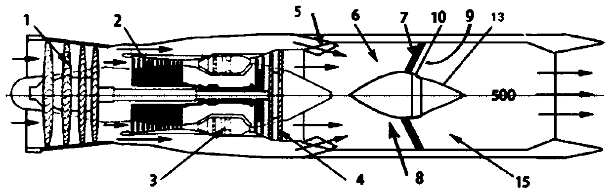
[0030] Such as figure 1 Shown is a structural diagram of a turbofan aero-engine that adopts a direct-injection fan nozzle and a concave cavity structure afterburner of the present invention. A fan 1 and a compressor 2 are sequentially arranged along the direction of air flow 100, that is, the central axis 500 of the gas turbine, and the air flows into the combustion chamber 3 after passing through the compressor; A blender 5 is arranged between the side walls of the afterburner chamber 15 , and a diffuser section 6 is formed between the blender 5 and the support plate 7 .

[0031] The structure after the turbine 4 belongs to the af...


PUM


Abstract

The invention discloses a direct-injection type fan-shaped nozzle applied to a cavity structure of an afterburner, relates to the direct-injection type fan-shaped nozzle which is installed in the cavity of the afterburner and used for enhancing fire stabilization performance and flame connection performance, and belongs to the field of aeroengines. According to the direct-injection type fan-shapednozzle applied to the cavity structure of the afterburner, a plurality of direct-injection type spray holes distributed in a certain shape are formed in the bottom end of each oil injection rod and used for spraying fuel into the cavity structure in the afterburner, the fuel forms a fan-shaped oil mist annular surface after being sprayed and atomized through the shape of the holes, the fan-shapedoil mist surfaces of every two adjacent oil injection rods intersect, and an oil mist ring concentric with a casing is formed in the cavity structure. The fuel atomization effect is enhanced, the circumferential flame connection performance is enhanced, and the combustion efficiency is improved. The direct injection type fan-shaped nozzle is small in machining difficulty, high in machining precision and small in nozzle hole diameter, so that the fuel atomization effect is good, and the overall performance of the afterburner is greatly improved.

Description

technical field [0001] The invention belongs to the field of fuel atomization of aero-engines, and relates to a direct-shooting fan nozzle with simple structure and convenient processing, which is installed in the cavity of an afterburner chamber and enhances the ability to stabilize fire and cross-flame. Direct fan nozzle with concave cavity structure. Background technique [0002] The invention of the nozzle structure is to turn a certain liquid into a droplet atomization structure. According to the atomization mechanism, it can be divided into pressure atomization and air atomization nozzles; according to the spray form, it can be divided into direct nozzles, cone nozzles, and fan nozzles. In the field of aero-engines, in order to organize the high-efficiency combustion of aviation kerosene in a small space and a short time, a centrifugal nozzle (belonging to the pressure atomization nozzle) is usually used to couple the air swirler to form a fuel-air mixture in the main...

Claims


Application Information

Patent Timeline
Patent Type & Authority Applications(China)
IPC IPC(8): F23R3/28
CPCF23R3/28
Inventor 李伟颜应文邸东李井华刘勇
Owner NANJING UNIV OF AERONAUTICS & ASTRONAUTICS
Why Eureka
Try Eureka