
Multi-shaft door frame forming device

A molding equipment and door frame technology, applied in sawing equipment, wood processing equipment, circular saws, etc., can solve the problems of many operators, loading and unloading errors, and low processing accuracy of molding products, and improve the processing safety factor , the use of less labor, the effect of high processing precision

Inactive Publication Date: 2013-03-13
宜昌盼盼木制品有限责任公司
View PDF6 Cites 2 Cited by
  • Summary
  • Abstract
  • Description
  • Claims
  • Application Information

AI Technical Summary

Problems solved by technology

The existing problems are: the molding products have many operators, many processes, large errors, high cost and low efficiency
And there are errors in the loading and unloading of different equipment, resulting in low processing accuracy

Method used


Image

  • Multi-shaft door frame forming device
  • Multi-shaft door frame forming device
  • Multi-shaft door frame forming device

Examples


Embodiment Construction

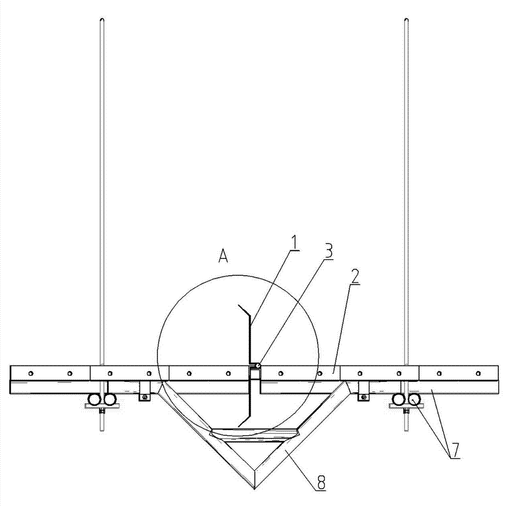
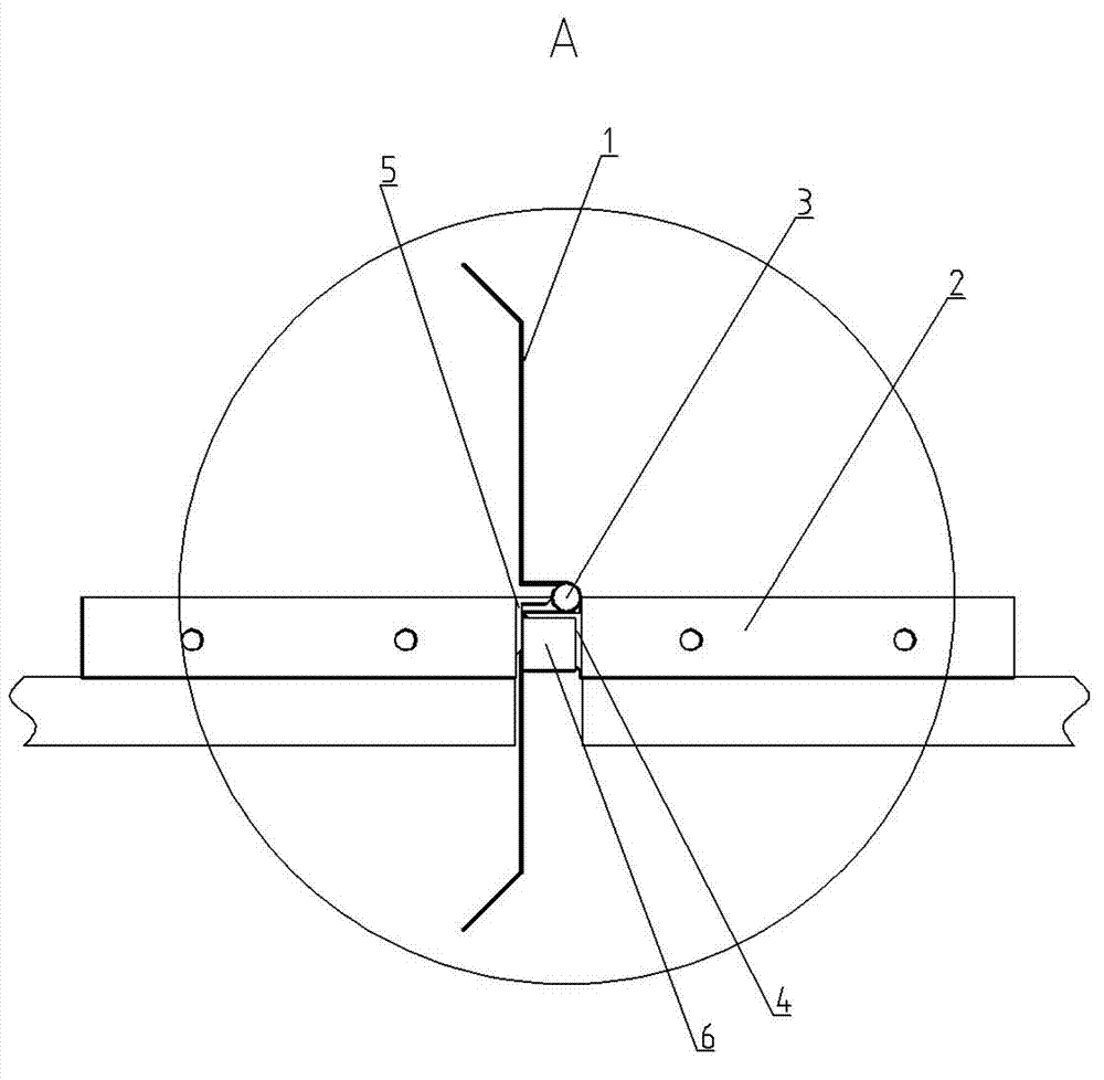
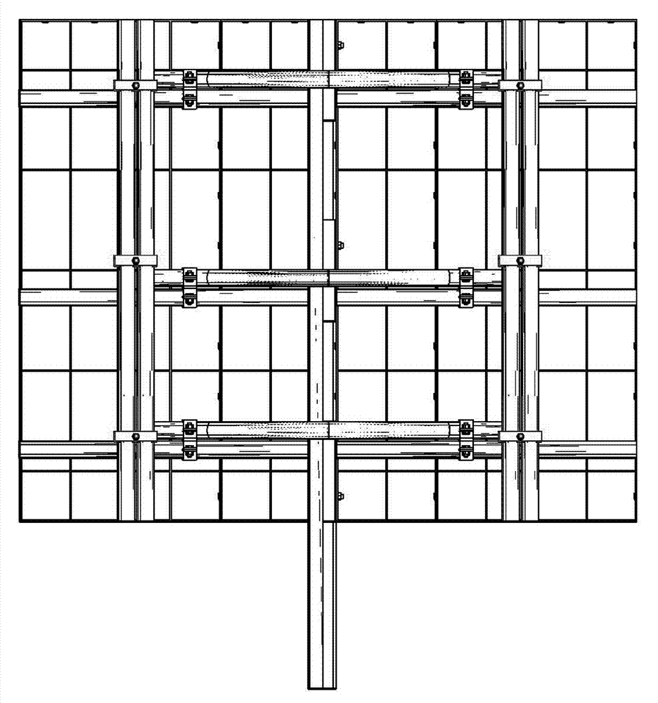
[0030] like figure 1 , 2 Among them, a multi-axis door frame forming equipment includes a frame 10, and the frame 10 is provided with a plurality of saw blades connected to the motor. A plurality of saw blades are arranged along the feed channel.

[0031] In an optimized solution, the motor is slidably connected to a base with a horizontal guide rail, and the base with a horizontal guide rail is slidably connected to the frame 10 through a vertical guide rail;

[0032] In another optional solution, or the motor is slidably connected to the base with vertical guide rails, and the base with vertical guide rails is slidably connected to the frame 10 through horizontal guide rails. This structure is more conducive to automatic control adjustment.

[0033] Other optional solutions are to replace the guide rails with horizontal or vertical grooves, for example, the motor is slidably connected to the base with the horizontal chute through bolts, and the base with the horizontal chu...


PUM


Abstract

The invention relates to a multi-shaft door frame forming device, which comprises a stander, wherein the stander is provided with a plurality of saw blades which are connected with a motor, the motor is connected with the stander in a way that the motor can move forwards and backwards and leftwards and rightwards, and the plurality of saw blades is are distributed along a feeding channel. Through the above structure, multiple machining procedures can be automatically completed in one step, and the simplicity in operation can be realized. The multi-shaft door frame forming device has the advantages of fast speed, high machining precision, low cost, high efficiency, less labor and high machining safety coefficient.

Description

technical field [0001] The invention relates to a door frame forming device, in particular to a multi-axis door frame forming device for one-time processing of door frame side strips in a sawing manner. Background technique [0002] The existing woodworking door frame processing equipment adopts a single-machine single-process processing method. The normal solid wood door frame processing specifications and sizes need at least 3--5 processes to complete. For example: first push the table saw to cut both sides, and the vertical axis milling machine No. 1 cuts the door , The vertical axis milling machine No. 2 saw the right line groove, the vertical axis milling machine No. 3 saw the left line groove, and the vertical axis milling machine No. 4 saw the sealing strip groove. And the processing safety factor is low. Most manufacturers need 4 processes, 4 sets of equipment, and 8 people to operate to ensure production needs. Existing problems are: the molded product has many op...

Claims


Application Information

Patent Timeline
Patent Type & Authority Applications(China)
IPC IPC(8): B27B5/065B27B5/34
Inventor 刘志勇李军学
Owner 宜昌盼盼木制品有限责任公司
Learn More