
Supersonic combustor wall surface concave cavity structure and engine combustor comprising same

A technology of supersonic combustion chambers and combustion chambers, which is applied in the direction of combustion chambers, continuous combustion chambers, combustion methods, etc., and can solve problems such as difficult thermal protection and large resistance

Active Publication Date: 2013-03-13
NAT UNIV OF DEFENSE TECH
View PDF7 Cites 35 Cited by
  • Summary
  • Abstract
  • Description
  • Claims
  • Application Information

AI Technical Summary

Problems solved by technology

[0012] 3. The scheme of increasing the penetration of fuel injection to enhance combustion requires the installation of support plates and other components, which will generate greater resistance and cause great difficulties for thermal protection

Method used


Image

  • Supersonic combustor wall surface concave cavity structure and engine combustor comprising same
  • Supersonic combustor wall surface concave cavity structure and engine combustor comprising same
  • Supersonic combustor wall surface concave cavity structure and engine combustor comprising same

Examples


Embodiment Construction

[0034] Hereinafter, the present invention will be described in detail with reference to the drawings and examples. It should be noted that, in the case of no conflict, the embodiments in the present application and the features in the embodiments can be combined with each other.

[0035] In this embodiment, taking the flow direction of air in the combustion chamber as a reference direction, the inflow direction of air is upstream, and the outflow direction is downstream. Take the plane where the bottom wall of the concave cavity is located as the horizontal plane, and the plane perpendicular to the horizontal plane as the longitudinal plane.

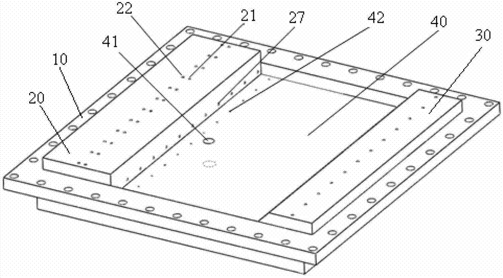
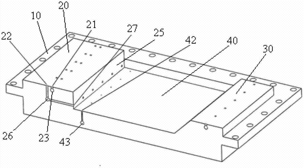
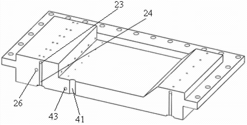
[0036] Such as Figure 1 to Figure 4 As shown, according to the embodiment of the present invention, the supersonic combustion chamber wall concave cavity structure includes a mounting seat 10, a combustion chamber wall concave cavity 40 is arranged in the mounting seat 10, and the upstream of the combustion chamber wall concave cavity ...


PUM


Abstract

The invention provides a supersonic combustor wall surface concave cavity structure and an engine combustor comprising the same. The supersonic combustor wall surface concave cavity structure comprises a mounting base (10), wherein a combustor wall surface concave cavity (40) is arranged in the mounting base (10); the upstream of the combustor wall surface concave cavity (40), positioned on the air inlet side, is equipped with a flow guiding hole (22); and correspondingly, the downstream of the flow guiding hole (22) is equipped with a concave cavity upstream fuel spray hole (21); the concave cavity upstream fuel spray hole (21) is nearer to the flow guiding hole (22); the downstream of the concave cavity upstream fuel spray hole (21) is equipped with a flow guiding hole outlet (27) which is communicated with the flow guiding hole (22); and the flow guiding hole outlet (27) is communicated with the concave cavity upstream fuel spray hole (21). The supersonic combustor wall surface concave cavity structure provided by the invention has a simple structure, can urge the ignition of fuels in the concave cavity before the ignition, and can reinforce the jet combustion of the fuels after the ignition.

Description

technical field [0001] The invention relates to the technical field of engine ignition, in particular to a supersonic combustion chamber wall concave cavity structure and an engine combustion chamber containing the same. Background technique [0002] Concave flame stabilizers are widely used in scramjet combustion chambers. The supersonic airflow flowing through the concave cavity will form a recirculation zone in the concave cavity, which can keep the flame in it all the time, and continue to ignite the upstream fuel as a new ignition source, so as to achieve flame stabilization. The concave cavity can integrate fuel injection, mixing enhancement and flame stabilization in the supersonic combustion chamber, and plays an important role in improving the performance of the scramjet engine. [0003] Fuel injection / ignition / flame stabilization / cooling integrated concave cavity, which is common in engineering at present, includes the integration of fuel injection, ignition, and ...

Claims


Application Information

Patent Timeline
IPC IPC(8): F23R3/00
Inventor 孙明波王振国梁剑寒刘卫东喻清
Owner NAT UNIV OF DEFENSE TECH
Learn More