Method for on-line diagnosing gradually-changing fault of electronic current transformers

An electronic transformer and current transformer technology, applied in the field of gradual fault online diagnosis, can solve problems such as staying in regular power outage maintenance and so on.

Active Publication Date: 2013-03-13
CHONGQING UNIV
View PDF3 Cites 12 Cited by
  • Summary
  • Abstract
  • Description
  • Claims
  • Application Information

AI Technical Summary

Problems solved by technology

In view of the lack of research on the identification of the operating status of electronic transformers, and its monitoring is still at the level of regular power outage maintenance, o

Method used


Image

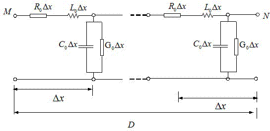
  • Method for on-line diagnosing gradually-changing fault of electronic current transformers
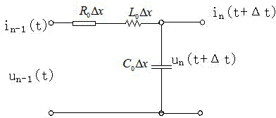
  • Method for on-line diagnosing gradually-changing fault of electronic current transformers
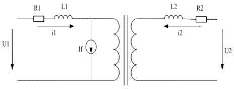
  • Method for on-line diagnosing gradually-changing fault of electronic current transformers

Examples


Example Embodiment

[0175] Experimental example 1: On March 7, 2011, the monitoring data is shown in Table 1 below

[0176] Table 1 Comparison of residuals

[0177]

[0178] As can be seen in Table 1, the residual error of each transmission line and transformer is less than the threshold ε 0 , Which shows that there is no gradual failure of the electronic current transformer in the substation, and there is no fault after field detection, which proves that the judgment is correct. The experimental results verify the accuracy of the electronic current transformer fault diagnosis method of the present invention.

Example Embodiment

[0179] Experimental Example 2: On June 28, 2011, the monitoring data is shown in Table 2 below

[0180] Table 2 Comparison of residuals

[0181]

[0182] As can be seen in Table 2, line 1 starts from the third sampling point, and the residual ε b1 Respectively 0.021I 0 , 0.023I 0 , 0.024I 0 , 0.025I 0 , 0.026I 0 , 0.025I 0 , 0.026I 0 , 0.027I 0 , Both exceed the set threshold ε 0 , The calculated residuals on other lines and transformers do not exceed the threshold ε 0 , Indicating that there is a gradual failure of the electronic current transformer on line 1, and there is no gradual failure of the electronic current transformer on line 2, line 3, and transformer. Perform Kirchhoff test on the sampling instantaneous values ​​of the electronic current transformers on all branches of the busbar of this substation, and the test result is greater than 0.027I 0 , That is, the vector sum of the current flowing into the bus is greater than ε 0 , Which means that the electronic current tra...

Example Embodiment

[0183] Experimental example 3: On August 16, 2011, the monitoring data is shown in Table 3 below

[0184] Table 3 Comparison of residuals

[0185]

[0186] It can be seen from Table 3 that line 3 starts from the fourth sampling point, and the residual ε b3 Respectively 0.022I 0 , 0.021I 0 , 0.022I 0 , 0.023I 0 , 0.025I 0 , 0.027I 0 , 0.026I 0 , Both exceed the set threshold ε 0 , The calculated residuals on other lines and transformers do not exceed the threshold ε 0 , Indicating that there is a gradual failure of the electronic current transformer on line 3, and there is no gradual failure of the electronic current transformer on line 1, line 2, and transformer. Perform Kirchhoff test on the sampling instantaneous values ​​of electronic current transformers on all branches of the busbar of this substation, and the test result is less than ε 0 , That is, the vector sum of the current flowing into the bus is less than ε 0 , Which means that the electronic current transformer with gra...


PUM


Abstract

A method for on-line diagnosing gradually-changing fault of electronic current transformers comprises the following steps: collecting output signals of electronic transformers of a whole transformer substation, calculating instant value of theoretical current at the tail ends of power transmission lines and on secondary sides of transformers at any moment, comparing the instant value of the theoretical current with the corresponding collected value, respectively calculating residual errors of the electronic current transformers at the front and tail end of each power transformation line and the primary side and the secondary side of each transformer, judging whether gradually-changing fault occurs on the electronic current transformers by comparing the residual errors with preset threshold values, and simultaneously performing Kirchhoff detection by injecting current into a busbar to position a fault transformer. The method is easy and convenient to operate, high in calculation accuracy, and capable of achieving on-line diagnosis on the gradually-changing fault under the condition that the electronic current transformers have no power failure or offline and require no other additional hardware device.

Description

(1) Technical field [0001] The invention relates to an online diagnosis method for gradual faults of electronic current transformers. (two), background technology [0002] With the construction and promotion of smart substations, the application of electronic transformers is becoming more and more extensive. Due to performance degradation and harsh on-site environment of electronic transformers operating in the field, there are often measurement errors between the output and the value under ideal conditions, which reduces the reliability of power supply. Since the principle of the electronic transformer is very different from that of the electromagnetic transformer, its reliability will also present some new features. The electronic transformers that are actually hung on the grid do not run for a long time, and most of them have a high failure rate, and they are still in the early failure stage of the products. After long-term operation in harsh environments, the performanc...

Claims


Application Information

Patent Timeline
IPC IPC(8): G01R35/02
CPCG01R35/02G01R31/62
Inventor 何建军罗建徐瑞林王洪彬陈涛高晋张友强张晓勇钟加勇刘祖建李杰王瑞妙魏甦蒋昆徐鑫朱特余红欣魏燕
Owner CHONGQING UNIV
Why Eureka
Try Eureka