Method and arrangement for driving a microphone

A microphone and generator technology, applied in electrostatic transducer microphones, amplifiers with semiconductor devices/discharge tubes, amplifiers, etc., to achieve the effect of eliminating overload

Active Publication Date: 2013-03-13
RES ELECTRONICS LEKSAND
View PDF4 Cites 2 Cited by
  • Summary
  • Abstract
  • Description
  • Claims
  • Application Information

AI Technical Summary

Problems solved by technology

Another problem with known solutions is the size of the microphone preamplifier circuit

Method used


Image

  • Method and arrangement for driving a microphone
  • Method and arrangement for driving a microphone
  • Method and arrangement for driving a microphone

Examples


Embodiment Construction

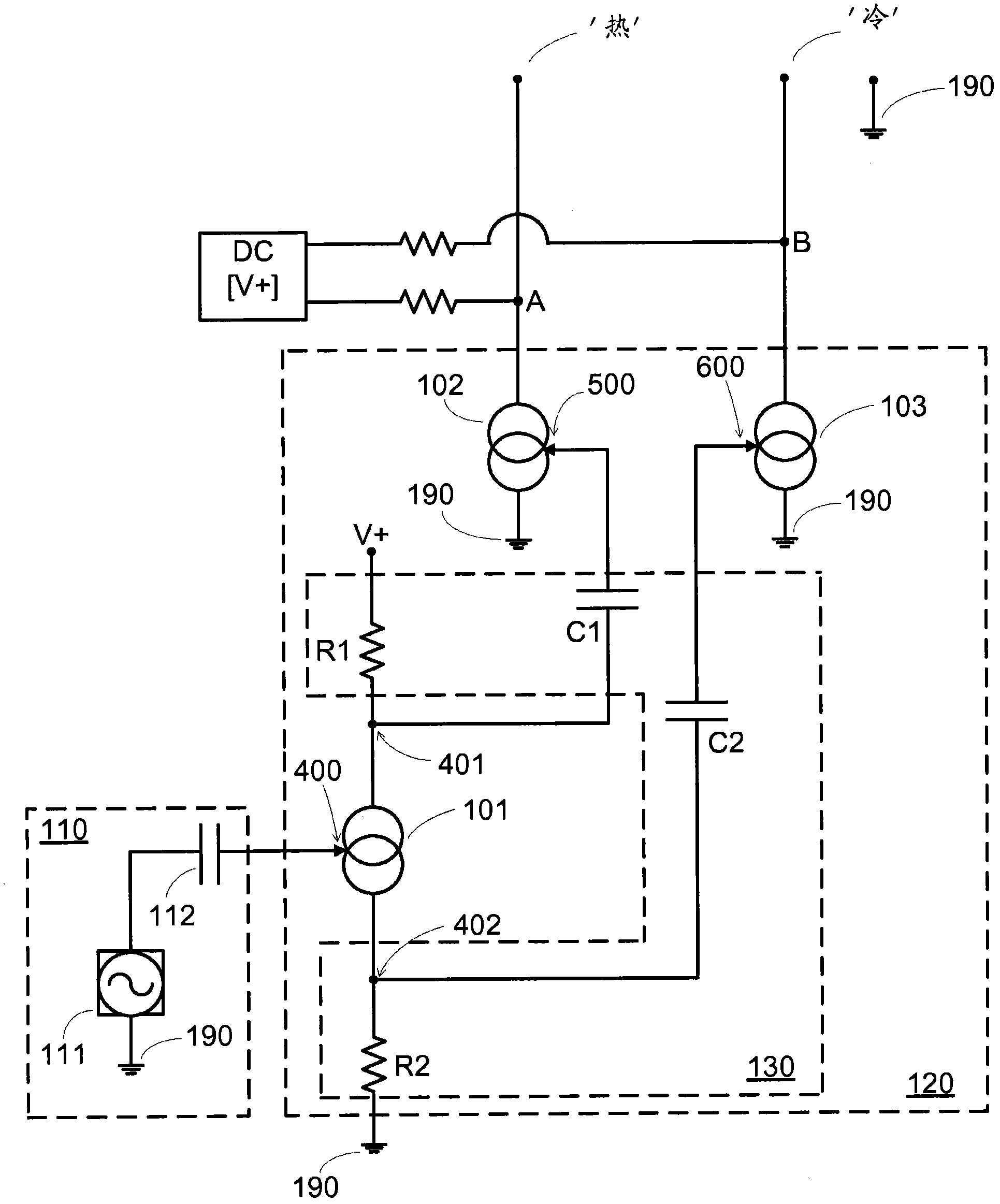
[0013] figure 1 A differential microphone preamplifier 120 implemented in accordance with an exemplary embodiment of the present invention and coupled to a microphone (MIC) 110 is shown. The differential microphone preamplifier 120 and the microphone (MIC) 110 are in one embodiment of the invention housed in the same housing, which is not shown in the figure. Furthermore, the microphone 110 may have additional signal amplification circuits which are not shown here for the sake of clarity. In operation, by virtue of its structure, a signal voltage is generated by the microphone element 111 of the microphone 110 and fed to the input 400 of the microphone preamplifier circuit 120 via the input coupling capacitor 112 . That is, the signal voltage is generated as a potential difference between the signal ground potential 190 and the voltage potential generated by the microphone element 111 . The microphone preamplifier circuit 120 will be described in more detail below, and the s...


PUM


Abstract

Disclosed is a differential microphone pre-amplifier circuit (120) for providing an amplified differential signal at a first (A) and a second (B) output terminal of the microphone pre- amplifier (120), including a first voltage controlled current generator (101), a second voltage controlled current generator (102) and a third voltage controlled current generator (103) all being configured to receive, amplify and convert a voltage signal generated by an associated microphone (110) to a current signal output.

Description

technical field [0001] The present invention relates to preamplifiers. In particular, the invention relates to high impedance output preamplifier circuits for microphones. Background technique [0002] In the early history of microphones only vacuum tube based amplifiers were available. The high output impedance of vacuum tubes, along with the high voltage required to drive them, on the order of 100 volts DC, forced engineers to use transformer-based coupling to drive the low-impedance inputs of typical mixer stages. [0003] Conventionally, microphone assemblies include a microphone element and a preamplifier circuit in a fixed arrangement within a common housing. The microphone assembly usually also includes an output terminal, in which the signal generated by the microphone element and amplified by the microphone preamplifier circuit is output. Because the power required to drive the vacuum tube microphone preamplifier circuit is so high, a separate power supply unit m...

Claims


Application Information

Patent Timeline
Patent Type & Authority Applications(China)
IPC IPC(8): H03F3/183H03F3/45H03F1/56H04R19/04
CPCH03F3/45076H03F3/183H03F2203/45228H03F2200/534
Inventor S-A・埃里克森
Owner RES ELECTRONICS LEKSAND
Why Eureka
Try Eureka