Forming die for machining method for high-strength transverse 8-shaped parts

A processing method and high-strength technology, applied in the field of metal stamping processing, can solve the problems such as difficulty in guaranteeing the precision and strength of mold processing, and the short service life of "∞"-shaped parts, so as to achieve the advantages of convenient operation for employees, stable stamping process, and improved precision Effect

Active Publication Date: 2013-03-20
黄山鼎奇链传动股份有限公司
View PDF10 Cites 2 Cited by
  • Summary
  • Abstract
  • Description
  • Claims
  • Application Information

AI Technical Summary

Problems solved by technology

[0003] The purpose of the present invention is to provide a molding die used in the processing method of high-strength "∞" shaped parts, which solves the problem that the processing accuracy and strength of existing molds are difficult to guarantee, and the service life of the obtained "∞" shaped parts is not long

Method used


Image

  • Forming die for machining method for high-strength transverse 8-shaped parts
  • Forming die for machining method for high-strength transverse 8-shaped parts
  • Forming die for machining method for high-strength transverse 8-shaped parts

Examples


Embodiment 1

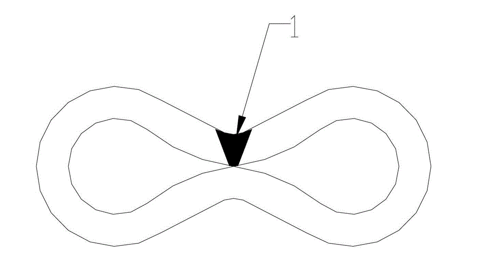
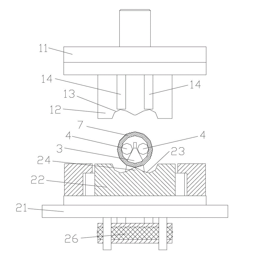
[0017] Example 1, please refer to Figures 1 to 3 , the molding die that is used for high-strength " ∞ " shape part processing method, comprises upper template 11, the upper mold 12 that is fixed on the upper template 11, lower template 21 and the lower mold 22 that are fixed on the lower template 21, described upper mold 12 is provided with an upper mold cavity 13, and the lower mold 22 is provided with a lower mold cavity 23. The upper mold cavity 13 and the lower mold cavity 23 cooperate to form a "∞"-shaped inner cavity; the lower mold cavity 22 is adapted to the lower mold cavity 23 The cavities on both sides of the middle position are respectively provided with a guide plate 3 and a pair of positioning rods 4 movable relative to the guide plate 3. The positioning rods 4 are stuck between the guide plate 3 and the inner wall of the metal pipe 7; , the positioning rod 4 can roll down along the edge of the guide plate 3, and finally fall into the "∞"-shaped inner cavity.

...

Embodiment 2

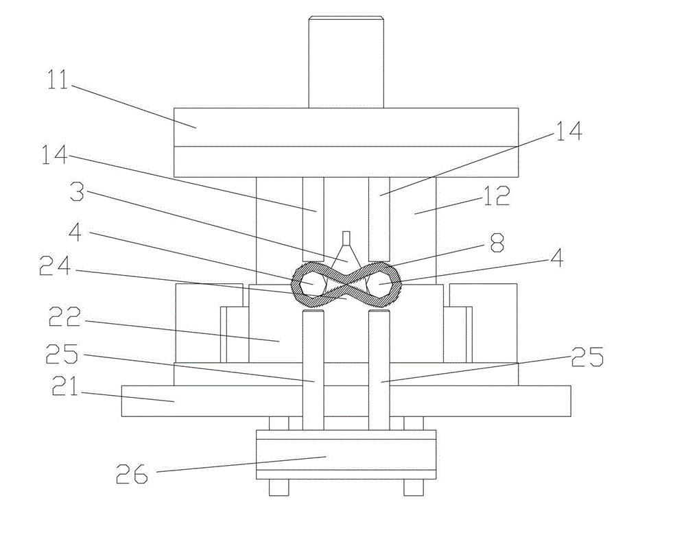
[0024] Please also refer to Figures 4 to 6 As shown, a support column 5 is also provided on the outside of the guide plate 3, and a compression spring 6 for controlling the stroke of the support column 5 is provided between the support column 5 and the lower template 21. The positioning rod 4 is placed on the support column 5, and the rest are the same as in embodiment 1. .

[0025] Place the heat-treated metal tube 7 on the lower mold 22 of the molding die, clamp the positioning rod 4 between the guide plate 3 and the inner wall of the metal tube 7, and place the positioning rod 4 on the support column 5, start the button, and the upper mold 12 goes down, when the upper die 12 presses the metal tube 7, the support column 5 goes down under the action of the compression spring 6, and the metal tube 7 is deformed at the same time, the positioning rod 4 rolls down along the edge of the guide plate 3, and finally falls into the "∞ "In the inner cavity of the font, the mold is mo...


PUM


Abstract

The invention discloses a forming die for a machining method for high-strength transverse 8-shaped parts. The forming die comprises an upper template, an upper die fixed on the upper template, a lower template and a lower die fixed on the lower template, wherein the upper die is provided with an upper die cavity; the lower die is provided with a lower die cavity; the upper die cavity is matched with the lower die cavity to form a transverse 8-shaped inner cavity; a guide plate and a pair of locating rods moving relative to the guide plate are arranged in two side cavities on the lower die adapted with the middle position of the lower die cavity respectively; and the locating rods are clamped between the guide plate and the inner wall of a metal tube. The forming die solves the problems that the machining accuracy of the current die cannot be ensured easily and the machined transverse 8-shaped parts have a short service life, and meets the requirement of a customer better.

Description

technical field [0001] The invention belongs to the field of metal stamping processing, and in particular relates to a forming die used in the processing method of high-strength "∞" shaped parts (such as chain inscribed). Background technique [0002] The "∞"-shaped part produced by the processing method of the present invention is an important connecting part on the chain, which is mainly used in high-power mechanical chains. Its precision and strength determine the quality and life of the entire chain. The existing processing methods are divided into welding type and casting type. The welding type process steps are flat strip cutting→pre-folding→primary bending→secondary bending→correction→welding sealing. The process of this process is long, the process is troublesome, and the delivery is often not up to the requirements, and the welding performance is poor, the workpiece is not easy to meet the technical requirements, and the life of the chain cannot be guaranteed. If t...

Claims


Application Information

Patent Timeline
Patent Type & Authority Applications(China)
IPC IPC(8): B21D37/10B21D45/00
Inventor 高坚胡爱忠凌荷梅葛建强黄波
Owner 黄山鼎奇链传动股份有限公司
Why Eureka
Try Eureka